Structure and enclosure combined modular equipment room

A kind of equipment room and modularization technology, which is applied in the direction of building components, building structure, construction, etc., can solve the problems that cannot meet the speed-up requirements of business expansion, the lifting requirements cannot be met, and large buildings cannot be transported, so as to achieve saving On-site construction period, light structure, and the effect of ensuring installation efficiency

Pending Publication Date: 2022-04-26
上海绿筑住宅系统科技有限公司 +1
View PDF0 Cites 0 Cited by
  • Summary
  • Abstract
  • Description
  • Claims
  • Application Information

AI Technical Summary

Problems solved by technology

During the construction process, construction waste and construction sewage are generated, and there is a lot of construction dust, which affects the surrounding environment. During the implementation of the new power distribution room, many changes are brought to the surrounding residents.
The most prominent problem is that the construction period of the traditional power distribution room is long and there is a lot of on-site work. It will take at least half a year to complete it all. The traffic in some areas is inconvenient, and large buildings cannot be transported. Large-scale machinery cannot be used for on-site construction. If it is not satisfied, it can only be assisted by manual or small machinery, which cannot meet the latest speed-up requirements for business expansion.
[0004] With the development of construction technology, many prefabricated steel structure power distribution rooms have been launched. Although the contradiction of the construction period has been alleviated to a large extent, the height of a single building is limited, the structure has a large weight, and the assembly accuracy is also affected by many factors. Influenced by various factors, the on-site construction process is complex and requires the cooperation of professionals, so it is technically difficult to promote it on a large scale

Method used


Image

  • Structure and enclosure combined modular equipment room
  • Structure and enclosure combined modular equipment room
  • Structure and enclosure combined modular equipment room

Examples


Embodiment

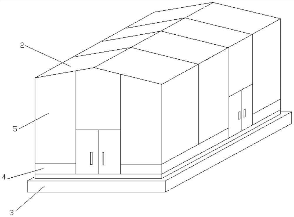
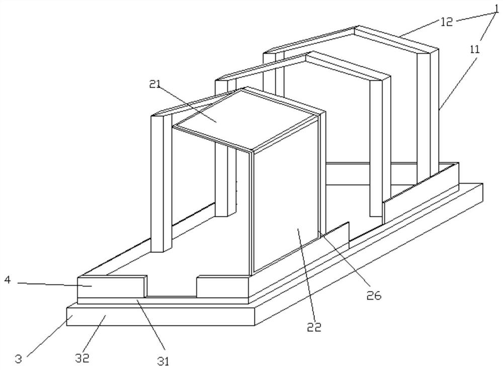
[0033] Embodiment: A modular equipment room with structure and enclosure combination, such as Figure 1-5 As shown, the equipment room as a whole is composed of folding roof and wall composite panels, bottom frame or frame chassis, lightweight concrete strips and door and window composite panels. According to the requirements of transportation size, they can divide the equipment room into several independent modules. The equipment room can be built with different groups of folding roof and wall composite panels according to the size, so as to make the structure universal and facilitate unified production.

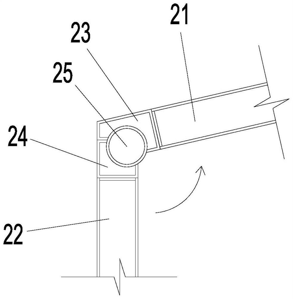
[0034]When the portal steel frame structure is added, the structure includes steel columns and steel beams, which are connected by full bolts. The structure is reliable, the installation is convenient, and it meets the requirements of large bays in the equipment room.

[0035] Frame chassis, including the chassis as the ground foundation and the bottom frame that defines th...


PUM


Abstract

The invention relates to the technical field of buildings, and discloses a structure and enclosure combined modular equipment room. The composite board comprises a frame chassis, a folding type house wall surface composite board, a lightweight concrete batten and a door and window composite board, the folding type house wall surface composite board and the door and window composite board are corrosion-resistant, fireproof, heat-insulating, decorative and structural integrated boards, and the bottom of the folding type house wall surface composite board is fixed to the frame chassis. The door and window composite boards are installed on the two sides of the folding type house wall face composite board, and an equipment room is built. The modular equipment room is an integrated system, design, production, transportation, installation and site are considered in an integrated mode, components and materials needed by the site are integrated in a frame chassis through the modular equipment room, expansion and combination work can be conducted on the site, and the site installation process and the site installation technology are simplified.

Description

technical field [0001] The invention relates to the field of building technology, in particular to a modular equipment room with a combination of structure and enclosure. Background technique [0002] In recent years, with the rapid development of cities, residents have increasingly higher requirements for the quality of power supply services, resulting in higher requirements for the safety and stability of the power grid. However, the power distribution facilities in many places cannot keep up with the needs of citizens, which brings great inconvenience to residents in using electricity. For this reason, many places have started to upgrade and add power distribution rooms to better receive, distribute, control and protect electric energy, and improve the reliability of power supply. [0003] The traditional power distribution room is constructed as a cast-in-place concrete structure or a steel-concrete structure, which is difficult to supervise in terms of construction tec...

Claims


Application Information

Patent Timeline
Patent Type & Authority Applications(China)
IPC IPC(8): E04B1/343E04B1/344E04B1/61E04B1/66E04B7/00
CPCE04B1/343E04B1/344E04B1/61E04B1/66E04B7/00E04B1/34315E04B1/612
Inventor 邵雪丽孙吉华秦建锋田香云潘韧坚张世斌宋飞贾立东张小俊史威艾月乔张舒吴琼魏义昕余冬王宁刘雅潘志榆唐岩杨全博
Owner 上海绿筑住宅系统科技有限公司
Why Eureka
Try Eureka