CSP heating furnace flue gas recirculation waste heat recovery system

A waste heat recovery system and flue gas recirculation technology, applied in heat treatment furnaces, lighting and heating equipment, furnaces, etc., can solve the problems affecting the heat exchange effect of heat exchange equipment, affecting the heat exchange absorption effect and heat exchange efficiency of heat exchange equipment, Trouble and other problems, to achieve the effect of avoiding adhesion deposition, avoiding the formation of scale, and prolonging the circulation time

Active Publication Date: 2022-04-26
江苏道和环保科技有限公司 +1
View PDF5 Cites 0 Cited by
  • Summary
  • Abstract
  • Description
  • Claims
  • Application Information

AI Technical Summary

Problems solved by technology

[0004]1) The flue gas discharged from the CSP heating furnace also contains some dust particles, but the existing waste heat recovery system neglects to filter the flue gas before heat exchange , so that under the accumulation of flue gas circulation for a long time, more flue gas dust particles will adhere to the heat exchange contact surface of the heat exchange equipment, thus affecting the heat exchange absorption effect and heat exchange efficiency of the heat exchange equipment
[0005]2) Water is used as the heat exchange medium. Scale components are generally unavoidable in the water. The heat exchange water in the heat exchange equipment in the traditional waste heat recovery system is naturally Therefore, after long-term heat exchange and circulation, especially when the water source itself contains more scale components, it will quickly accumulate and solidify inside the heat exchange equipment to form a layer of scale, and the scale will gradually thicken , the thicker scale layer will naturally affect the heat exchange effect of the heat exchange equipment. In addition, it is necessary to manually clean the scale regularly, which is troublesome

Method used


Image

  • CSP heating furnace flue gas recirculation waste heat recovery system
  • CSP heating furnace flue gas recirculation waste heat recovery system
  • CSP heating furnace flue gas recirculation waste heat recovery system

Examples


Embodiment Construction

[0036] The specific embodiment of the present invention will be described in further detail by describing the embodiments below with reference to the accompanying drawings, the purpose is to help those skilled in the art to have a more complete, accurate and in-depth understanding of the concept and technical solutions of the present invention, and To facilitate its practice, but not as a limitation of the invention.

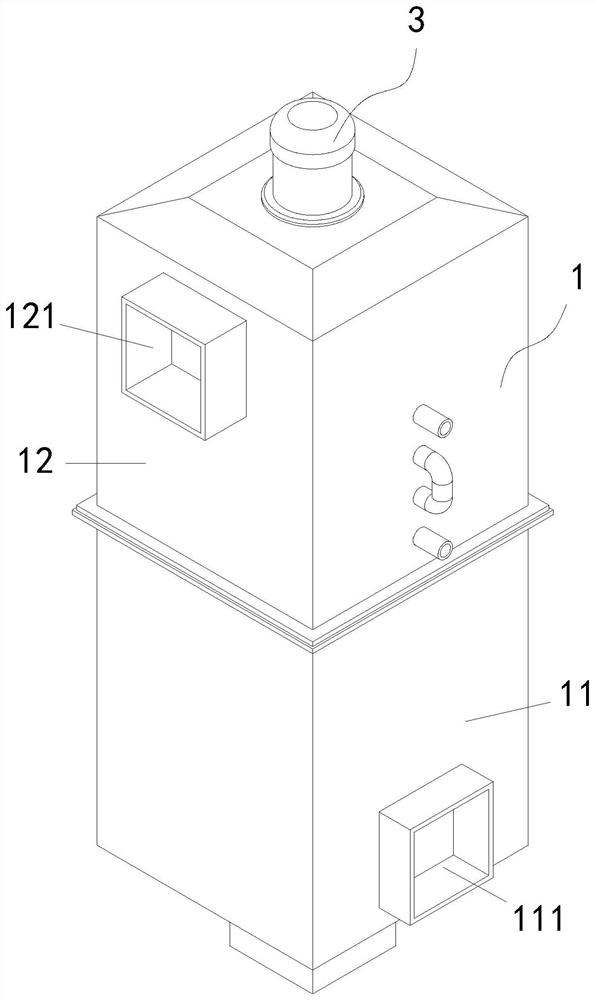
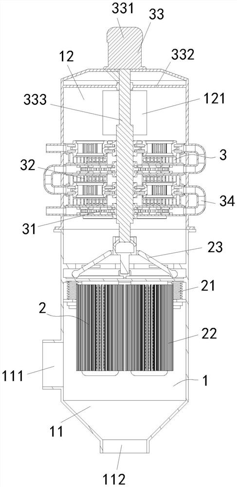
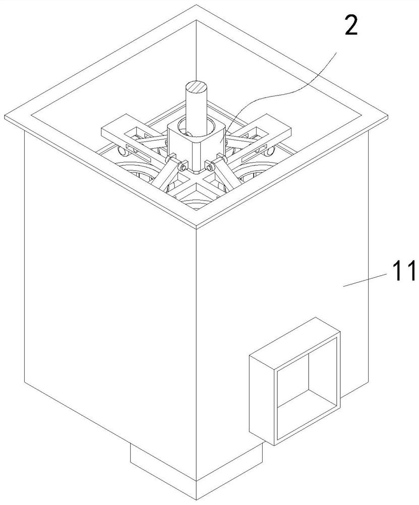
[0037] Such as figure 1 and figure 2 As shown, a CSP heating furnace flue gas recirculation waste heat recovery system includes a working chamber 1, a flue gas filtering device 2 and a waste heat recovery device 3; the working chamber 1 includes a square filter chamber 11 and is welded and fixed on the top of the filter chamber 11 The recovery bin 12 is a square structure, the flue gas filter device 2 is assembled in the filter bin 11, and the waste heat recovery device 3 is assembled on the recovery bin 12; An ash bin 112 is provided at the bottom of the bin...


PUM


Abstract

The invention relates to the technical field of waste heat recovery, in particular to a CSP heating furnace flue gas recirculation waste heat recovery system which comprises a working bin, a flue gas filtering device and a waste heat recovery device. The working bin comprises a square filtering bin and a recycling bin which is fixedly communicated with the top end of the filtering bin and is of a square structure, the smoke filtering device is assembled in the filtering bin, and the waste heat recycling device is assembled on the recycling bin; according to the system provided by the invention, flue gas filtration is additionally arranged before waste heat recovery, so that the problem that waste heat exchange recovery is influenced by adhesion and deposition of flue gas dust particles is avoided, meanwhile, incrustation cleaning can be actively carried out in real time, and the influence of an incrustation layer on the heat exchange effect is avoided or reduced.

Description

technical field [0001] The invention relates to the technical field of waste heat recovery, and specifically proposes a waste heat recovery system for flue gas recirculation of a CSP heating furnace. Background technique [0002] CSP is the abbreviation of Compact Strip Production, the English full name of the compact tropical production technology. It is a relatively mature typical thin rice billet continuous casting and rolling process in the existing steel forming process. Heating equipment for heating and preheating thin slabs. In the actual production and operation process, the heat energy utilization efficiency of the CSP heating furnace is not high when heating thin slabs. If waste heat is not recovered, a large amount of residual heat will Automatic discharge will cause a large waste of energy and ineffective loss of production costs. Therefore, existing steel profile manufacturers have begun to pay attention to waste heat recovery from thermal energy equipment such ...

Claims


Application Information

Patent Timeline
Patent Type & Authority Applications(China)
IPC IPC(8): F27D17/00F27D25/00F28G3/10C21D9/70
CPCF27D17/004F27D17/008F27D25/001F28G3/10C21D9/70Y02P10/20Y02P10/25
Inventor 方国红
Owner 江苏道和环保科技有限公司
Why Eureka
Try Eureka