Supercharge Your Innovation With Domain-Expert AI Agents!

High-voltage high-precision large-current piezoelectric ceramic constant-current driving circuit

A piezoelectric ceramic, constant current drive technology, applied in the direction of adjusting electrical variables, instruments, control/regulating systems, etc., can solve problems such as slow dynamic response speed, reduce static power consumption, improve dynamic response characteristics, and widely popularize The effect of applying value

Active Publication Date: 2022-04-26
BEIHANG UNIV
View PDF4 Cites 2 Cited by
  • Summary
  • Abstract
  • Description
  • Claims
  • Application Information

AI Technical Summary

Problems solved by technology

[0004] 1. Purpose of the invention: For piezoelectric ceramics with high mechanical properties and large capacitance, there are problems such as slow dynamic response speed when driven by a small current constant current power supply. The present invention is based on DSP digital processing, photoelectric isolation, and high-precision digital-analog Conversion, power amplification, MOSFET constant current amplification, digital closed-loop control and other technologies provide a high-voltage, high-precision, high-current piezoelectric ceramic constant-current drive circuit, which can not only output a large current of more than ten amperes, and greatly improve the dynamic response of the system characteristics, and the output voltage can be as high as hundreds of volts or even thousands of volts according to the selected MOSFET power tube withstand voltage. At the same time, the high-precision control of the charging and discharging current and voltage of piezoelectric ceramics is realized through current and voltage digital closed-loop feedback adjustment.

Method used


Image

  • High-voltage high-precision large-current piezoelectric ceramic constant-current driving circuit
  • High-voltage high-precision large-current piezoelectric ceramic constant-current driving circuit
  • High-voltage high-precision large-current piezoelectric ceramic constant-current driving circuit

Examples


Embodiment Construction

[0079] The present invention provides a high-voltage, high-precision, and high-current piezoelectric ceramic constant-current drive circuit, and its specific implementation method is:

[0080] The high-voltage, high-precision, and high-current piezoelectric ceramic constant-current drive circuit includes:

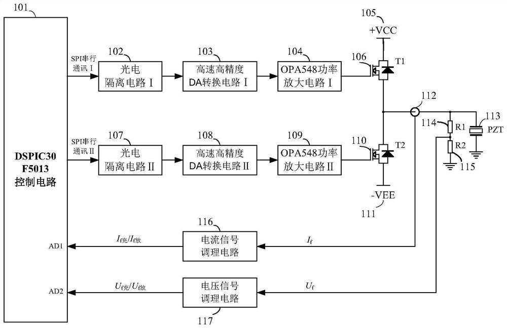
[0081] see figure 1As shown, DSPIC30F5013 control circuit (101), photoelectric isolation circuit Ⅰ (102), high-speed high-precision DA conversion circuit Ⅰ (103), OPA548 power amplifier circuit Ⅰ (104), piezoelectric ceramic charging drive power supply + VCC (105), MOSFET power tube T1 (106), photoelectric isolation circuit II (107), high-speed high-precision DA conversion circuit II (108), OPA548 power amplifier circuit II (109), MOSFET power tube T2 (110), piezoelectric ceramic discharge drive power supply -VEE (111), current sensor (112), piezoelectric ceramics (113), voltage divider resistor R1 (114), sampling resistor R2 (115), current signal conditioning circuit (116...


PUM


Abstract

The invention discloses a high-voltage high-precision large-current piezoelectric ceramic constant-current driving circuit. The high-speed high-precision DA conversion circuit comprises a DSPIC30F5013 control circuit (101), a photoelectric isolation circuit I (102), a high-speed high-precision DA conversion circuit I (103), an OPA548 power amplification circuit I (104), a piezoelectric ceramic charging driving power supply + VCC (105), an MOSFET (Metal-Oxide-Semiconductor Field Effect Transistor) power tube T1 (106), a photoelectric isolation circuit II (107), a high-speed high-precision DA conversion circuit II (108), an OPA548 power amplification circuit II (109), an MOSFET power tube T2 (110), a piezoelectric ceramic discharging driving power supply-VEE (111), a current sensor (112), piezoelectric ceramics (113), a voltage divider resistor R1 (114) and a sampling resistor R2 (115). A current signal conditioning circuit (116) and a voltage signal conditioning circuit (117); the high-voltage high-precision large-current piezoelectric ceramic constant-current driving circuit is scientific in structure and good in manufacturability, and has wide popularization and application values.

Description

technical field [0001] The invention provides a high-voltage, high-precision, high-current piezoelectric ceramic constant-current drive circuit, in particular a high-voltage, high-precision constant-current drive circuit for driving a piezoelectric ceramic micro-displacer, belonging to the technical field of special power supplies. Background technique [0002] The inverse piezoelectric effect of piezoelectric ceramics can be used to make micro-displacement actuators, which have the advantages of high resolution, small size, fast response, and large thrust. They are widely used in micro-displacement output devices, valve control, force generating devices, robots, Impact motor, optical scanning and other important fields. With the wide application of piezoelectric ceramics and the increasing demand for high-precision positioning, higher requirements are also put forward for piezoelectric ceramic drive power. At present, most piezoelectric ceramic drivers use high-voltage ope...

Claims


Application Information

Patent Timeline
IPC IPC(8): G05F1/56
CPCG05F1/56
Inventor 张伟黄俊媛蒋布辉
Owner BEIHANG UNIV
Features
  • R&D
  • Intellectual Property
  • Life Sciences
  • Materials
  • Tech Scout
  • Unparalleled Data Quality
  • Higher Quality Content
  • 60% Fewer Hallucinations
Learn More