Mechanical mill crusher

A pulverizer and mechanical technology, applied in the field of pulverizers and mechanical mill pulverizers, can solve the problems of unstable pulverized materials, short use time of wearing parts, low graphite pulverization capacity, etc., achieve stable material size and structure, and save energy. Effect

Inactive Publication Date: 2022-04-29
鸡西德立重工金属结构制造有限公司
View PDF5 Cites 0 Cited by
  • Summary
  • Abstract
  • Description
  • Claims
  • Application Information

AI Technical Summary

Problems solved by technology

[0003] The purpose of the present invention is to solve the problems of low production capacity, high energy consumption, short service

Method used


Image

  • Mechanical mill crusher
  • Mechanical mill crusher
  • Mechanical mill crusher

Examples


specific Embodiment approach 1

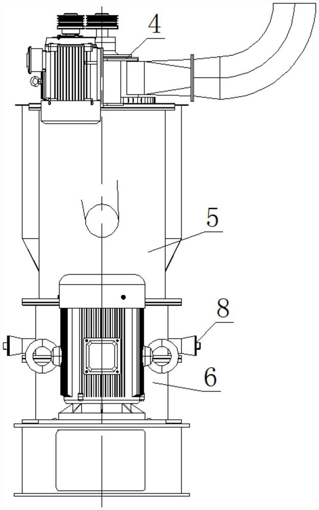
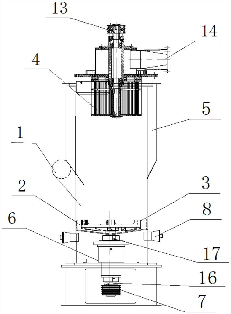
[0019] Specific implementation mode one: combine Figure 1-Figure 8 To illustrate this embodiment, a mechanical mill pulverizer provided in this embodiment includes a classifier 4, a box body 5, a mechanical mill assembly 6, a mechanical mill pulley 7, a classifier pulley 13 and a discharge pipe 14; The mechanical grinding assembly 6 is installed on the bottom of the box body 5, the mechanical grinding pulley 7 is set on the input end of the mechanical grinding assembly 6, the mechanical grinding pulley 7 is connected with the driving parts through a belt, and the classifier 4 is installed on the box body 5 On the top of the top of the classifier, the classifier pulley 13 is set on the input end of the classifier 4, and the discharge pipe 14 is installed on the classifier 4 above the box body 5. The box body 5 is provided with a feed port 1, and the classifier pulley 13 passes through A belt is connected to the drive member.

[0020] In this embodiment, the rotation direction...

specific Embodiment approach 2

[0021] Specific implementation mode two: combination Figure 1-Figure 4 The present embodiment is described. In the mechanical mill pulverizer provided in this embodiment, the impeller of the classifier 4 is arranged in the box body 5, and the annular sealing plate at the top of the impeller and the sealing plate at the bottom of the cyclone collector are arranged through a labyrinth seal. The input end of the classifier 4 rotating shaft is fixedly inserted on the classifier pulley 13, and the output end of the classifier 4 rotating shaft passes through the cyclone collector and is fixedly connected with the impeller. Other structural connections are the same as in the first embodiment.

[0022] During the work of this application, the processed graphite below is sorted by the impeller of the classifier 4. After processing, the graphite that meets the specifications enters the cyclone collector, and the graphite that does not meet the specifications falls into the mechanical g...

specific Embodiment approach 3

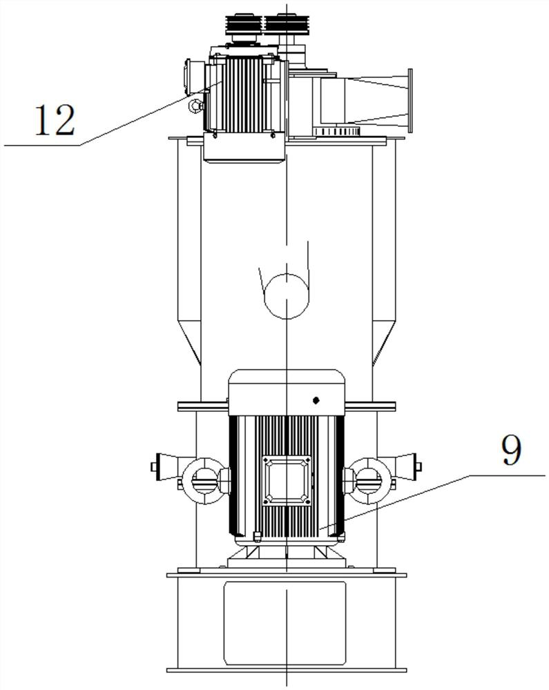
[0023] Specific implementation mode three: combination Figure 1-Figure 4 The present embodiment is described. In the mechanical mill pulverizer given in the present embodiment, the drive components include a mechanical mill motor 9 and a classifier motor 12. The output end of the classifier motor 12 is equipped with a drive pulley, and the classifier motor 12 housing Close to the classifier 4 and installed on the box body 5, the driving pulley on the classifier motor 12 and the classifier pulley 13 are connected by multiple belt transmissions, and the output end of the mechanical grinding motor 9 is equipped with a driving pulley. The housing of the mechanical grinding motor 9 is installed on the On the casing 5, the driving pulley of the mechanical grinding motor 9 and the mechanical grinding pulley 7 are connected through a plurality of belt transmissions. Other structural connections are the same as in the second embodiment.


PUM

PropertyMeasurementUnit
Sizeaaaaaaaaaa

Abstract

The invention relates to a superfine mechanical mill crusher, in particular to a mechanical mill crusher, which aims to solve the problems of low productivity, high energy consumption, short service time of quick-wear parts and unstable materials in graphite crushing production, and comprises a grader, a box body, a mechanical mill assembly, a mechanical mill belt pulley, a grader belt pulley and a discharge pipe, the mechanical mill assembly is installed at the bottom end of the box body, the input end of the mechanical mill assembly is sleeved with the mechanical mill belt wheel, the mechanical mill belt wheel is connected with the driving component through a belt, the classifier is installed at the top end of the box body, the input end of the classifier is sleeved with the classifier belt wheel, and the discharging pipe is installed on the classifier above the box body. A feeding port is formed in the box body, and the grader belt pulley is connected with the driving component through a belt. The invention belongs to the field of graphite mechanical grinding.

Description

technical field [0001] The invention relates to a pulverizer, in particular to a mechanical pulverizer. It belongs to the field of industrial graphite ultrafine mechanical powder. Background technique [0002] With the advancement of social productivity, the pulverizer is widely used in all walks of life. The pulverizer is a kind of crushing operation that applies mechanical force to the solid material. The material is sent to the crushing chamber of the main machine by the feeding device; Under the action of the high-pressure and high-frequency pulsating cyclone flow generated by the high-speed rotary device, the particles are driven by the cyclone flow to rotate, thus forming several large and small swirl flows, and the materials, high-speed rotary devices and particles are extruded, collided, rubbed, and sheared. And achieve ultra-fine crushing. After the material is pulverized by the pulverizer, its particle size gradually decreases, and finally reaches the required pa...

Claims


Application Information

Patent Timeline
IPC IPC(8): B02C19/00B02C23/20
CPCB02C19/0018B02C19/0043B02C19/005B02C23/20
Inventor 杨立涛夏德波
Owner 鸡西德立重工金属结构制造有限公司
Why Eureka
Try Eureka