Dust control and removal method and system for driving face of driving and anchoring all-in-one machine

A technology of excavation working face and dust removal system, which is applied in the directions of dust prevention, bolt installation, earthwork drilling and mining, etc. It can solve the problem that it is difficult to realize the efficient collection and treatment of flour dust in excavation work, and it is impossible to realize the erection of hard air ducts and the treatment effect Poor and other problems, to achieve the effect of solving serious dust hazards, high promotion value, efficient collection and treatment

Pending Publication Date: 2022-04-29
CHINA COAL TECH ENG GRP CHONGQING RES INST
View PDF0 Cites 0 Cited by
  • Summary
  • Abstract
  • Description
  • Claims
  • Application Information

AI Technical Summary

Problems solved by technology

The supporting equipment of the tunneling working face of the integrated drilling and bolting machine is different from that of the traditional fully mechanized tunneling working face. The integrated drilling and bolting machine is often used in combination with a bolter trolley and a self-moving tail to meet the needs of drilling and supporting while tunneling. The equipment has no solid connection, and due to the limitation of the roadway space, the all-in-one machine is equipped with a small hydraulic dust removal fan, which has limited air volume and poor treatment effect
At the same time, due to the large size of the integrated bolter and bolter trolley, the effective section of the roadway is almost blocked, and it is impossible to erect a hard air duct and extend the dust suction port to the position where the integrated bolter is close to the head, making it difficult to realize the integrated bolter Efficient Collection and Treatment of Flour and Dust in Machine Excavation

Method used


Image

  • Dust control and removal method and system for driving face of driving and anchoring all-in-one machine

Examples


Embodiment

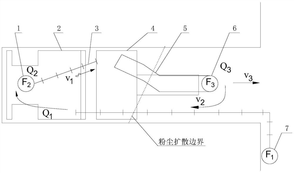
[0031] A control and dust removal system for the excavation working face of an all-in-one machine for digging and bolting, such as figure 1 As shown, F1 is the local air supply fan 7, Q1 is the air supply volume of the excavation surface; F2 is the dust extraction fan 1 designed and fixed on the bolt-digging integrated machine 2, and the air suction volume is Q2; F3 is the dust removal fan 6, and the processing air volume is Q3; The air volume is: Q3>Q1>Q2. Since Q3 is the largest, the head-on air supply volume is smaller than the hard air duct suction volume, a part of the air volume from the air outlet of the dust removal fan 6 enters the exhaust system at a speed of v3, and the other part of the air volume flows to the front at a speed of v2, and the direction is from the roadway to the front. At this time, the stroke from the F3 position to the dust extraction port of the hard negative pressure dust extraction duct 5 is a negative pressure area, which creates the effect of...


PUM

PropertyMeasurementUnit
Lengthaaaaaaaaaa

Abstract

The invention relates to a dust control and removal method and system for a driving working face of a driving and anchoring all-in-one machine, and belongs to the technical field of mine dust control. Dust generated in the production process of the driving and anchoring all-in-one machine is moved to the rear side of the driving and anchoring all-in-one machine or an anchor rod trolley, so that the problem that the production process is limited by the driving working face of the driving and anchoring all-in-one machine is solved; and then, dust treatment is carried out through a high-power dust removal fan which moves along a slide way along with the digging and anchoring integrated machine. According to the invention, a mode of'moving dust at first and post-treating 'is adopted, and large dust removal equipment is post-positioned, so that the problems caused by space limitation are solved, the treatment air volume is larger, efficient collection and treatment of dust on the driving working face of the driving and anchoring integrated machine are realized, the theoretical dust falling rate reaches 100%, and the actual dust falling efficiency can reach more than 90%; and the working environment can be obviously improved. In addition, the method has the advantage of low cost and high popularization value.

Description

technical field [0001] The invention belongs to the technical field of mine dust prevention and control, and relates to a method and a system for controlling and removing dust from a tunneling working face of an integrated machine for digging and bolting. Background technique [0002] As the mechanization of excavation equipment is getting higher and higher, modern large-scale mines have appeared integrated excavation and support machines, which have achieved a monthly excavation of more than 2000m, greatly promoted the tunnel excavation speed, and eased the excavation. imbalance problem. However, it is accompanied by the problem of high-concentration dust hazards. When the daily footage increases several times and the ventilation rate basically does not change, the dust concentration of the tunneling face of the integrated tunneling machine is several times higher than that of the fully-mechanized tunneling face. The first disaster factor in the tunneling face of the ancho...

Claims


Application Information

Patent Timeline
IPC IPC(8): E21F5/20E21F1/08E21F17/00E21D9/10E21D20/00
CPCE21F5/20E21F1/08E21F17/00E21D9/10E21D20/00
Inventor 庄学安李德文马威杨俊磊袁地镜张设计胥奎郭胜均郑磊冉川黎志杨桐陈芳莫金明李腾龙韩汉张帆刘国庆李岳程丽王迪陈真
Owner CHINA COAL TECH ENG GRP CHONGQING RES INST
Why Eureka
Try Eureka