
Permanent magnet synchronous motor with protection structure

A technology for permanent magnet synchronous motors and protection structures, applied in electromechanical devices, electrical components, electric components, etc., can solve problems such as internal circuit damage, poor heat dissipation of devices, and impact on service life, and achieve poor shock absorption and improved The effect of damping performance

Pending Publication Date: 2022-04-29
JIAXING UNIV
View PDF13 Cites 4 Cited by
  • Summary
  • Abstract
  • Description
  • Claims
  • Application Information

AI Technical Summary

Problems solved by technology

While reducing the overall volume and weight of the explosion-proof motor, the invention can also reduce the temperature rise of the bearing, reduce the failure rate, and reduce the maintenance cost, so as to meet the requirement of heat dissipation while meeting the requirement of miniaturization of the external dimension of the motor , to adapt to market development and market demand", but the heat dissipation of the device is poor. When the permanent magnet synchronous motor works for a long time, it will emit a lot of heat. If it is not cooled in time, it will easily damage its internal circuit, thus affecting its use. life

Method used


Image

  • Permanent magnet synchronous motor with protection structure
  • Permanent magnet synchronous motor with protection structure
  • Permanent magnet synchronous motor with protection structure

Examples


Embodiment Construction

[0035] The following will clearly and completely describe the technical solutions in the embodiments of the present invention with reference to the accompanying drawings in the embodiments of the present invention. Obviously, the described embodiments are only some, not all, embodiments of the present invention. Based on the embodiments of the present invention, all other embodiments obtained by persons of ordinary skill in the art without making creative efforts belong to the protection scope of the present invention.

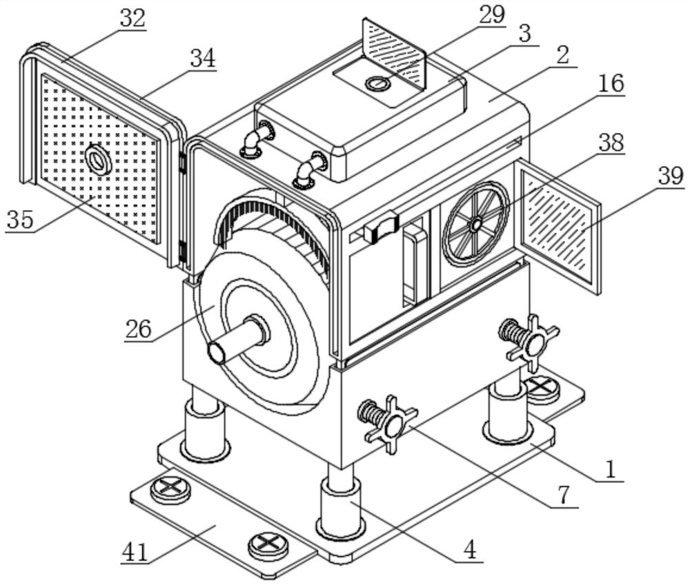
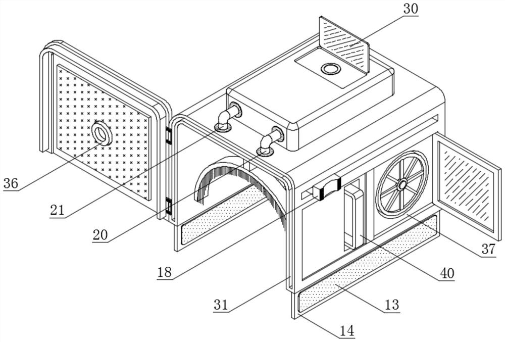
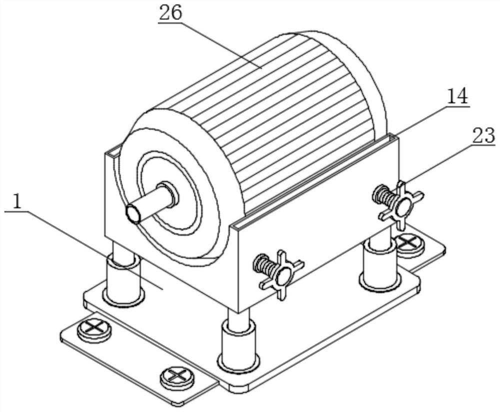
[0036] see Figure 1-8 , an embodiment provided by the present invention: a permanent magnet synchronous motor with a protective structure, including a fixed plate 1, a protective shell 2 and a water storage bin 3, and a support sleeve 4 is installed around the top of the fixed plate 1, The inside of the support sleeve 4 is provided with a damping spring 5, the top of the damping spring 5 is connected with a support rod 6, and the top of the support rod 6 is c...


PUM


Abstract

A permanent magnet synchronous motor with a protection structure disclosed by the present invention comprises a fixed plate, a protection shell and a water storage bin, a damping spring is arranged in a support sleeve, the top end of the damping spring is connected with a support rod, the top end of the support rod is connected with a fixed base, a movable rod is arranged in a movable clamp, and the fixed base is connected with a fixed base. And the top end of the movable rod is connected with a movable block. Through the arrangement of the damping springs and the elastic springs, after a worker puts the permanent magnet synchronous motor body into the fixed base, the self weight of the permanent magnet synchronous motor body and generated vibration press the supporting rods downwards to enable the damping springs to deform, and the damping springs can offset partial force with the permanent magnet synchronous motor body according to self elasticity; when the movable rod is stressed, the movable rod can drive the connecting rod to extrude the elastic spring so that the elastic spring can deform, the elastic spring can push the connecting rod towards the two sides according to the elasticity of the elastic spring, and therefore the buffering effect is achieved, and the damping performance of the device is further improved.

Description

technical field [0001] The invention relates to the technical field of permanent magnet synchronous motors, in particular to a permanent magnet synchronous motor with a protective structure. Background technique [0002] In order to achieve energy conversion, a synchronous generator needs a DC magnetic field, and the DC current that generates this magnetic field is called the excitation current of the generator. According to the supply mode of excitation current, any generator that obtains excitation current from other power sources is called an externally excited generator, and one that obtains excitation power from the generator itself is called a self-excited generator. The automatic adjustment excitation system can be regarded as a In the negative feedback control system with voltage as the adjusted quantity, the reactive load current is the main reason for the voltage drop of the generator terminal. When the excitation current remains unchanged, the terminal voltage of ...

Claims


Application Information

Patent Timeline
IPC IPC(8): H02K5/24H02K5/10H02K5/04H02K9/19H02K9/04H02K5/22H02K5/00B08B1/00
CPCH02K5/24H02K5/10H02K5/04H02K9/19H02K9/04H02K5/00H02K5/22B08B1/30B08B1/12
Inventor 胡劼李传宝赵浩李洪武董睿傅文珍刘春元王挺习聪玲
Owner JIAXING UNIV
Learn More