Camera module parameter recording method, vignetting adjusting method and device
A camera module and parameter recording technology, which is applied in the field of data processing, can solve the problems of vignetting, high cost, vignetting, etc., and achieve the effects of saving production costs, reducing errors, and improving production efficiency
- Summary
- Abstract
- Description
- Claims
- Application Information
AI Technical Summary
Problems solved by technology
Method used
Image
Examples
Embodiment 1
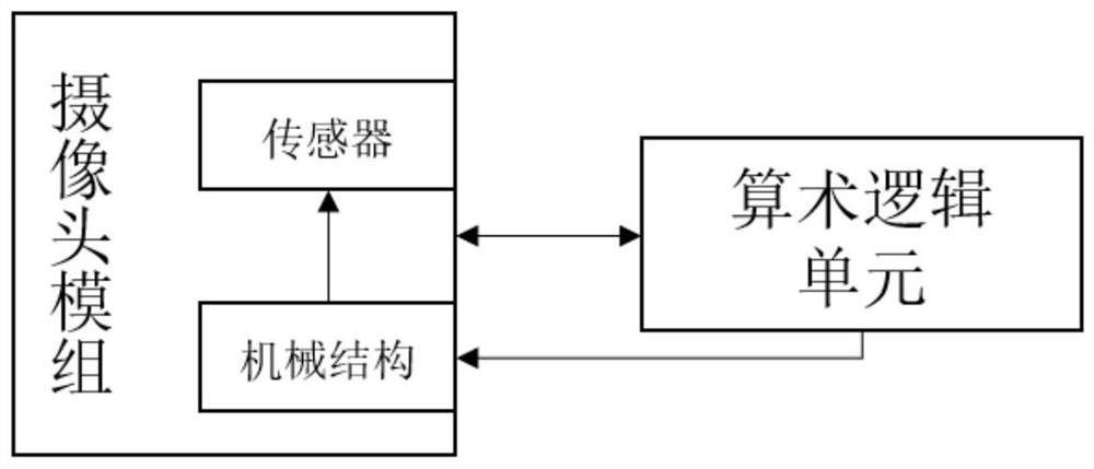
[0049] Camera module, full name Camera Compact Module, abbreviated as CCM. CCM consists of four major components: lens (lens), sensor (sensor), flexible board (FPC), and image processing chip (DSP). The important components that determine the quality of a camera are: lens (lens), image processing chip (DSP), sensor (sensor). The lens is composed of several lenses, which can image the scene to be shot on the sensor; the sensor is a device used to receive the light passing through the lens and convert the light signal into an electrical signal; DSP is a digital image through complex mathematical operations. After the signal is optimized, the signal is transmitted to the display. The working principle of the camera is mainly to shoot the scene through the lens, project the generated optical image onto the sensor, and the sensor will convert the optical image into an electrical signal, and the electrical signal is converted into a digital image signal by the internal image proces...
Embodiment 2
[0085] Corresponding to the method in Embodiment 1, the present invention also provides a method for adjusting the vignetting of the camera module, please refer to Figure 4 , Figure 4 It is a schematic flowchart of a method for adjusting a vignetting angle of a camera module provided in Embodiment 2 of the present invention, and the method includes step S410, step S420 and step S430. It should be noted that step S410, step S420 and step S430 are only reference numerals for clearly explaining the embodiment and the accompanying Figure 4 The corresponding relationship does not represent a limitation on the order of the steps in this embodiment.
[0086] Step S410, receiving the focal length to be adjusted.
[0087] Step S420, obtaining parameters to be adjusted according to the focal length to be adjusted; wherein, the adjustment parameters are obtained by the method described in Embodiment 1.
[0088] Step S430, adjusting the sensor according to the adjustment parameter. ...
Embodiment 3
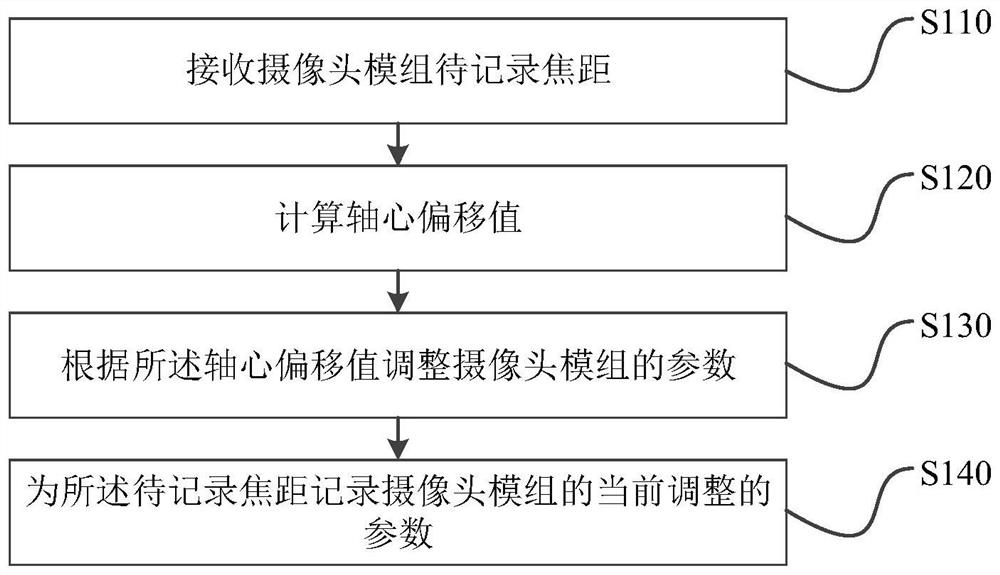
[0093] Corresponding to the method of embodiment one, such as Figure 5 As shown, the present invention also provides a camera module parameter recording device 5 , including: a receiving module 501 , a calculating module 502 , an adjusting module 503 and a recording module 504 .
[0094] The receiving module 501 is configured to receive the focal length to be recorded by the camera module, wherein the focal length to be recorded is one of multiple candidate focal lengths;
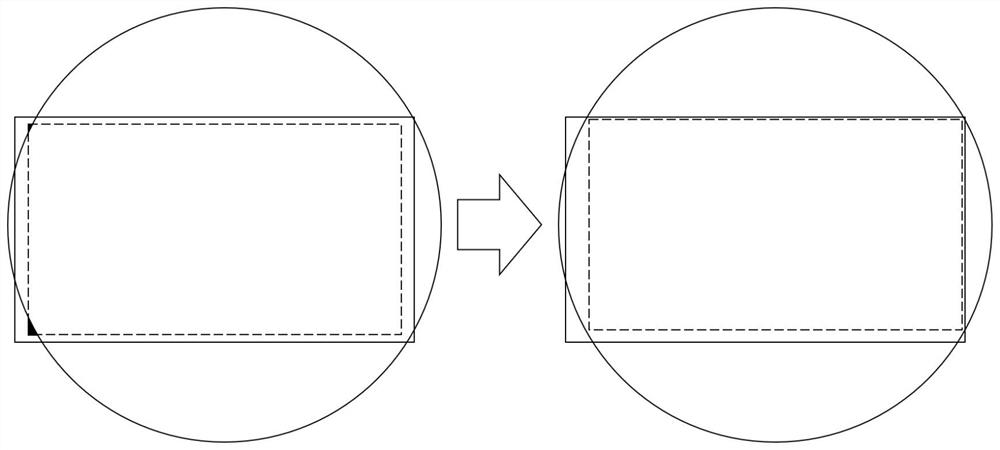
[0095] The calculation module 502 is used to calculate the axis offset value, wherein the axis offset value is the offset value of the center of the image capturing area of the sensor of the camera module relative to the lens optical center of the camera module;
[0096] An adjustment module 503, configured to adjust parameters of the camera module according to the axis offset value;
[0097] The recording module 504 is configured to record the currently adjusted parameters of the camera module for the ...
PUM
 Abstract
Description
Claims
Application Information
 - R&D
- Intellectual Property
- Life Sciences
- Materials
- Tech Scout
- Unparalleled Data Quality
- Higher Quality Content
- 60% Fewer Hallucinations
Browse by: Latest US Patents, China's latest patents, Technical Efficacy Thesaurus, Application Domain, Technology Topic, Popular Technical Reports.
© 2025 PatSnap. All rights reserved.Legal|Privacy policy|Modern Slavery Act Transparency Statement|Sitemap|About US| Contact US: help@patsnap.com


