Composite floor slab construction assembly

A technology for laminating floor slabs and components, applied in manufacturing tools, ceramic molding machines, molds, etc., can solve the problems of increasing the vibration deflection of the steel skeleton, difficult demoulding, and increasing the construction period, so as to improve the overall structural strength and improve the overall vertical degree, avoid vibration and skew effects

Pending Publication Date: 2022-05-06
ZHEJIANG YIJIAN CONSTR GROUP
View PDF0 Cites 1 Cited by
  • Summary
  • Abstract
  • Description
  • Claims
  • Application Information

AI Technical Summary

Problems solved by technology

[0003] (1) In the process of traditional laminated floor prefabrication construction, it is difficult to adapt to the prefabrication requirements of laminated floor slabs with different perimeter sizes, and it is difficult to realize the production and processing of laminated floor slabs with more complex cross-section forms, and in the process of prefabricated construction In the middle, it is difficult to clamp and position the steel skeleton in the laminated floor, which increases the possibility of vibration deflection of the steel skeleton caused by the impact in the subsequent concrete pouring process, and reduces the overall structural strength of the laminated floor
[0004] (2) During the traditional precast construction of laminated slabs, it is difficult to quickly dry the concrete in each area after pouring, which increases the overall solidification time of the laminated slab concrete, increases the prefabrication period, and is also difficult After the composite floor slab is prefabricated, it is quickly demoulded around it, which increases the possibility of collapse of the edge of the floor slab due to concrete bonding during the removal process of the composite floor slab

Method used


Image

  • Composite floor slab construction assembly
  • Composite floor slab construction assembly
  • Composite floor slab construction assembly

Examples


Embodiment Construction

[0033] In order to make the technical means, creative features, goals and effects achieved by the present invention easy to understand, the present invention will be further described below in conjunction with specific embodiments.

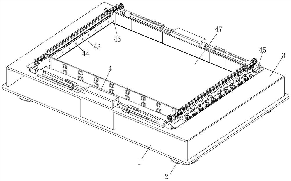
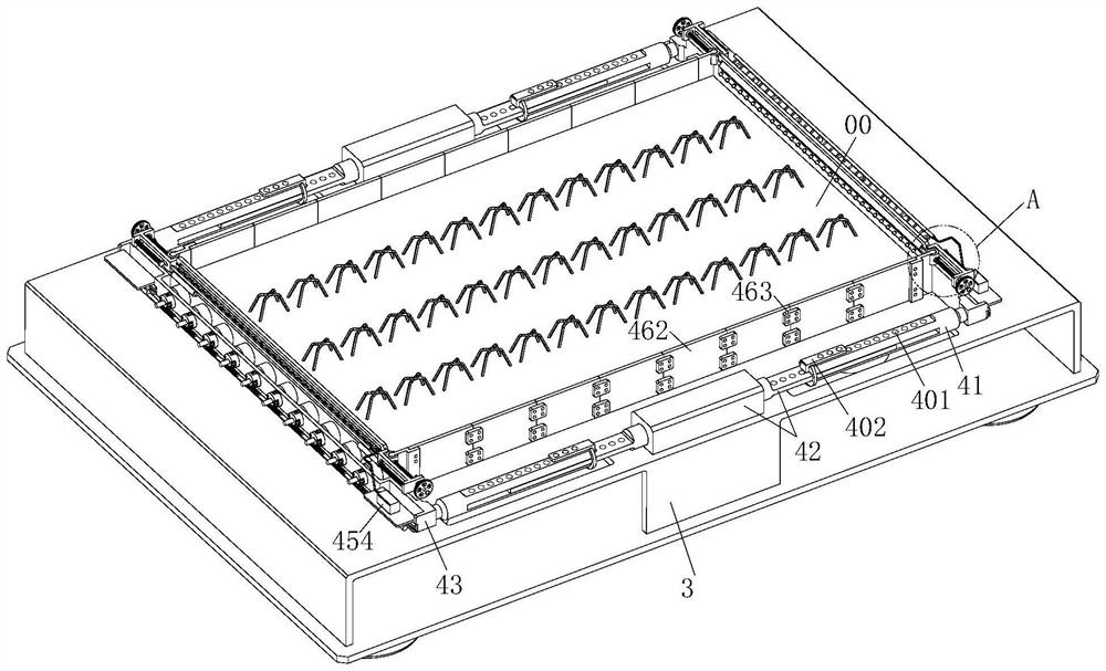
[0034] refer to figure 1 , figure 2 with Figure 4 , a construction assembly of a laminated floor 00 according to the present invention, comprising a base plate 1, a supporting foot 2, a frame 3, a forming mechanism 4 and a demoulding mechanism 5, and supports are installed at corners around the lower end of the base plate 1 Foot 2, the upper end of the base plate 1 is equipped with a 匚-shaped frame 3 with an opening downward, and a forming mechanism 4 is installed in the middle of the upper end of the 匚-shaped frame 3, and a demoulding mechanism 5 is installed on the 匚-shaped frame 3 and the base plate 1, and the demoulding The mechanism 5 is connected with the forming mechanism 4 in transmission.

[0035] refer to Figure 2 to Figure 9 , th...


PUM


Abstract

The invention relates to the field of composite floor slabs, in particular to a composite floor slab construction assembly which comprises a base plate, supporting legs, a [-shaped frame, a forming mechanism and a demolding mechanism. The problems that in the traditional composite floor slab prefabricating construction operation process, prefabricating requirements of composite floor slabs of various different perimeter sizes cannot be met easily, manufacturing and machining of the composite floor slabs with complex section forms cannot be achieved easily, and in the prefabricating construction process, clamping and positioning of steel reinforcement frameworks in the composite floor slabs cannot be achieved easily are solved. The possibility that the steel reinforcement framework vibrates and deflects due to impact in the follow-up concrete pouring process is increased, the overall structural strength of the composite floor slab is reduced, concrete in all areas is difficult to dry quickly after pouring is completed, the overall solidification time of the concrete of the composite floor slab is prolonged, and the construction period of the composite floor slab is shortened. And the periphery of the composite floor slab is difficult to demould quickly after the prefabrication of the composite floor slab is completed.

Description

technical field [0001] The invention relates to the field of laminated floor slabs, in particular to a construction component of laminated floor slabs. Background technique [0002] The laminated slab is an assembled integral slab formed by laminating prefabricated slabs and cast-in-place reinforced concrete layers. The laminated floor slab has good integrity, and the upper and lower surfaces of the slab are flat, which is convenient for decoration of the facing layer. It is suitable for high-rise buildings and large-bay buildings that require high overall rigidity. It acts as a formwork when pouring the upper concrete, and the latter two concrete parts form a whole to bear the load. Composite floor slab combines the advantages of cast-in-place and prefabrication, and is a promising floor form. From the perspective of manufacturing technology, post-cast concrete uses prefabricated bottom slabs as formwork, which can reduce formwork work compared with fully cast-in-place flo...

Claims


Application Information

Patent Timeline
Patent Type & Authority Applications(China)
IPC IPC(8): B28B7/02B28B11/24B28B13/06B28B23/02
CPCB28B7/02B28B23/02B28B11/245B28B13/067
Inventor 史磊贾承杰胡林生王帅铭宣淼波吴炫霖
Owner ZHEJIANG YIJIAN CONSTR GROUP
Why Eureka
Try Eureka