Robot flexible foot

A flexible foot and robot technology, which is applied in the field of humanoid robots, can solve the problems of complex structure, stuck cylinder and upper platen, etc., and achieve low raw material requirements, convenient kinematics modeling and dynamics simulation, and easy Achieved effect

Active Publication Date: 2022-05-06
ZHEJIANG LAB
View PDF14 Cites 0 Cited by
  • Summary
  • Abstract
  • Description
  • Claims
  • Application Information

AI Technical Summary

Problems solved by technology

This mechanism guarantees the shock absorption in the vertical direction, but the structure is complicated, and it is easy to cause jamming between the sole cylinder and the upper pressure plate

Method used


Image

  • Robot flexible foot
  • Robot flexible foot
  • Robot flexible foot

Examples


Embodiment 1

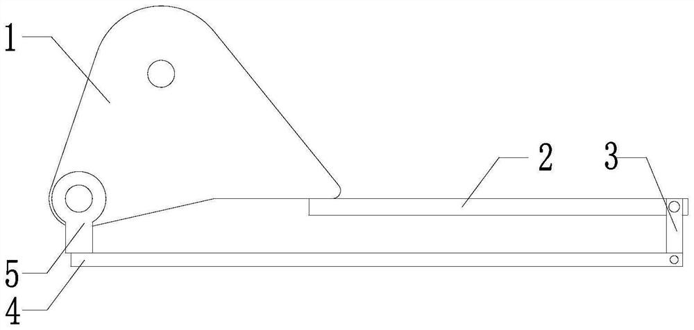
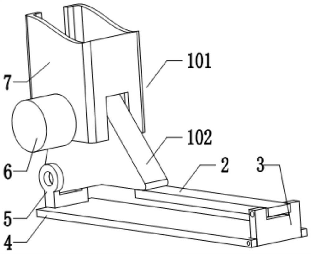
[0028] like figure 1 The shown flexible foot of a robot includes an ankle 1, a foot surface 2, a first connecting rod 3, a sole 4, and a second connecting rod 5 connected end to end in sequence. The foot surface 2 is an elastic plate, one end is fixedly connected to the ankle 1, and the other end is rotatably connected to the first connecting rod 3; one end of the sole 4 is rotatably connected to the first connecting rod 3, and the other end of the sole 4 is connected to the first connecting rod 3 One end of the second connecting rod 5 is fixedly connected, and the second connecting rod 5 is rotatably connected with the ankle 1 .

Embodiment 2

[0030] Based on the first embodiment, the foot surface 2 is an elastic plate, and the rotational connection between the foot surface 2 and the first connecting part 3 is changed to a fixed connection. It should be pointed out that no matter whether the elastic plate is fixedly connected or rotated, the connection is equivalent to a rotating connection. In this way, the three rotating pairs of this scheme can be reduced to two rotating pairs, and the subtracted rotating pair can be changed to for a fixed connection.

Embodiment 3

[0032] Based on the first embodiment, the elastic board is replaced with a rigid board, that is, the foot surface 2 adopts a rigid board. One end of the foot surface 2 is rotatably connected to the ankle 1 through a torsion spring, the other end of the foot surface 2 is rotatably connected to the first connecting rod 3, and the first connecting rod 3 is rotatably connected to one end of the sole 4, and the sole 4 The other end is fixedly connected with one end of the second connecting rod 5 , and the second connecting rod 5 is connected with the ankle 1 in rotation.


PUM


Abstract

The invention discloses a flexible foot of a robot, which solves the problem that the foot of the robot is in rigid contact with the ground, and comprises an ankle, a foot surface, a sole, a first connecting part, a second connecting part and a driving device, the ankle is provided with a foot kinematic pair and a driving part; the ankle, the foot surface, the first connecting part, the sole and the second connecting part are sequentially connected end to end, at least one of the foot surface, the first connecting part, the sole and the second connecting part is an elastic plate, and the elastic plate is fixedly connected with an adjacent component at one end of the elastic plate, so that the flexible foot forms a planar four-bar mechanism; the driving device acts on the driving part to drive the flexible foot to move around the foot kinematic pair, and the purpose that the foot of the robot makes elastic contact with the ground to reduce impact on an ankle motor is achieved.

Description

technical field [0001] The invention relates to the field of humanoid robots, in particular to a robot flexible foot. Background technique [0002] Humanoid robots have the advantages of strong ability to adapt to the environment and flexible movements. Therefore, they have broader application and development prospects. [0003] Stable walking is the key for a humanoid robot to achieve a high degree of flexibility. During the walking process of the robot, the reaction force of the ground to the robot is an important factor affecting the stability. This requires that the soles of the robot have the ability to conform to the ground and absorb the impact of the ground. [0004] Chinese Patent No. CN101402380A has invented a humanoid robot foot shock absorbing mechanism, including a sole plate, a shock-absorbing column is arranged on the sole of the foot, and a pressure plate is provided on the upper surface of the shock-absorbing column. A force sensor and an upper cover are...

Claims


Application Information

Patent Timeline
Patent Type & Authority Applications(China)
IPC IPC(8): B62D57/032
CPCB62D57/032
Inventor 陈令凯张兰谢也孔令雨黄冠宇谢安桓张丹
Owner ZHEJIANG LAB
Why Eureka
Try Eureka