A cutting fluid cooling and degreasing device for CNC machine tools for machining

A CNC machine tool and machining technology, applied in metal processing equipment, metal processing mechanical parts, manufacturing tools, etc., can solve the problems of metal swarf doping, single degreasing function, poor degreasing efficiency, etc., to achieve accelerated cooling , The connection structure is simple, and the effect of easy recycling

Active Publication Date: 2022-07-05
徐州宝恒智能科技有限公司
View PDF1 Cites 0 Cited by
  • Summary
  • Abstract
  • Description
  • Claims
  • Application Information

AI Technical Summary

Problems solved by technology

[0005] In order to solve the above technical problems, the present invention provides a cutting fluid cooling and degreasing device for numerically controlled machine tools for mechanical processing, so as to solve the problem that the cutting fluid often When the oil is removed through the adsorption layer, its degreasing function is single, resulting in poor degreasing efficiency of the equipment, and a large amount of metal chips are mixed in the cutting fluid, which is troublesome to collect and difficult to recycle. During the cooling process, the oil will solidify, causing a large amount of it to deposit on the side wall of the collection bucket, which requires frequent disassembly and cleaning of the collection bucket

Method used


Image

  • A cutting fluid cooling and degreasing device for CNC machine tools for machining
  • A cutting fluid cooling and degreasing device for CNC machine tools for machining
  • A cutting fluid cooling and degreasing device for CNC machine tools for machining

Examples


Embodiment 1

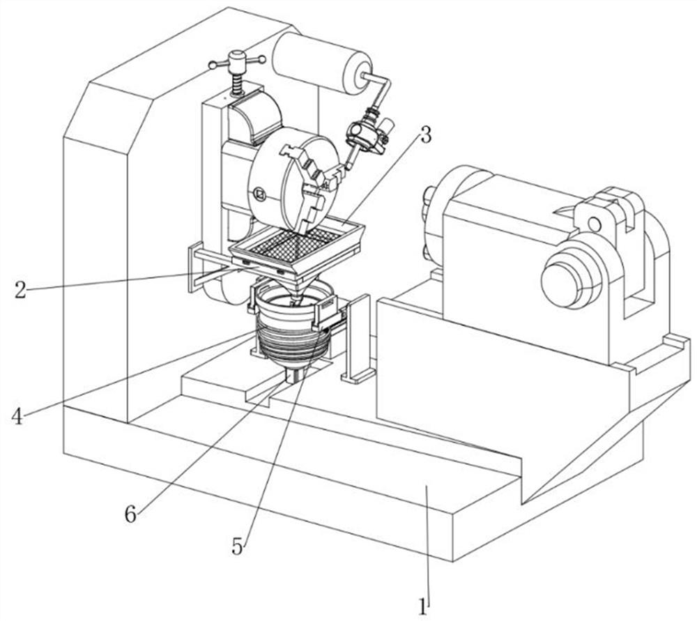
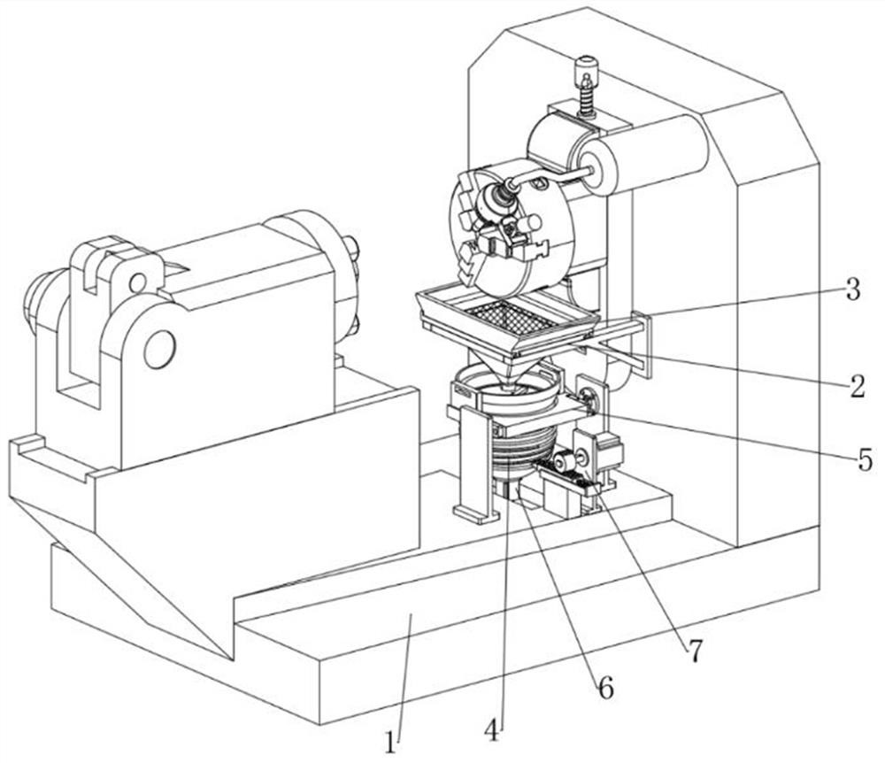
[0038] as attached figure 1 to the attached Image 6 Shown: the present invention provides a cutting fluid cooling and degreasing device for CNC machine tools for machining, comprising a worktable 1; a collection groove 2 is provided at the front end of the vertical frame of the worktable 1, and a mounting frame is provided on the collection groove 2 3; The top of the bottom frame of the workbench 1 is provided with a collection barrel 4, and the collection barrel 4 is provided with a turret 5, and the turret 5 is connected with the bottom frame of the workbench 1 through two vertical plates; the bottom of the collection barrel 4 is provided with There is a first servo motor 6 , a swing mechanism 7 is provided on the right side of the collecting barrel 4 ;

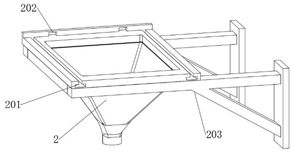
[0039] like image 3 and Figure 4 As shown, the collection tank 2 includes a first chute 201, a bayonet 202 and a support frame 203. The collection tank 2 is fixedly connected to the workbench 1 through the support fra...

Embodiment 2

[0044] like Figure 7 Shown: the rocking mechanism 7 includes a second servo motor 701, a missing gear 702, a sliding frame 703, a rack 704 and a compression spring 705. The end of the rotating shaft of the second servo motor 701 is provided with a missing gear 702, and below the missing gear 702 is provided There is a sliding frame 703, the sliding frame 703 is a rectangular groove structure, and the sliding frame 703 is provided with a rack 704, and a compression spring 705 is arranged between the rack 704 and the right end side wall of the sliding frame 703, and the gear 702 and the rack are missing. 704 is meshed and connected, and the left end of the rack 704 is rotatably connected to the collecting bucket 4 through a pin shaft. The device is powered by the second servo motor 701, and is driven by the missing gear 702 and the rack 704, and the rack 704 can slide along the sliding frame 703. At the same time, the rack 704 drives the collection bucket 4 to move in an arc wi...

Embodiment 3

[0046] like Figure 8 to Figure 10 Shown: the first servo motor 6 includes a rotating shaft 601 and a stirring blade disc 602, and a rotating shaft 601 is rotatably installed on the first servo motor 6, and the rotating shaft 601 penetrates the bottom of the collecting bucket 4 and is arranged in its interior, rotating The shaft 601 is provided with a stirring blade disk 602, and the stirring blade disk 602 is located in the oil removal cylinder 8; the oil removal cylinder 8 includes a fixing frame 801 and an adsorption cotton plate 802, and the oil removal cylinder 8 is a cylindrical through-cavity structure, and the removal of The bottom of the oil cylinder 8 is provided with an adsorption cotton plate 802, and the top of the oil removal cylinder 8 is provided with a fixed frame 801. The rotating shaft 601 penetrates the middle position of the suction cotton plate 802, and the rotating shaft 601 is rotatably connected with the fixed frame 801 through a bearing; 9 includes a ...


PUM


Abstract

The invention provides a cutting fluid cooling and degreasing device for CNC machine tools used for machining, which relates to the technical field of machining, so as to solve the problem that when the existing cutting fluid cooling and degreasing device for CNC machine tools is used for machining, cutting fluid is often used. The oil contamination is removed when passing through the adsorption layer, and its degreasing function is single. At the same time, during the cooling process of the cutting fluid, the oil contamination will solidify, causing a large amount of it to deposit on the side wall of the collection bucket. The collection bucket needs to be disassembled and cleaned frequently. It includes a workbench; the front end of the vertical frame of the workbench is provided with a collection groove, and the collection groove is provided with a mounting frame; the top of the bottom frame of the workbench is provided with a collection bucket. In the present invention, the rack drives the collection bucket to move in an arc with the rotating shaft of the turret as the axis, and uses the elastic action of the compression spring to realize the reciprocating swing action of the collection bucket. It cools down while avoiding oil deposits on the side walls of the collection tub.

Description

technical field [0001] The invention belongs to the technical field of machining, and more particularly relates to a cutting fluid cooling and degreasing device for CNC machine tools used for machining. Background technique [0002] In the field of machining, the cutting fluid circulation system is widely used in CNC machine tools, automatic metal processing equipment, sheet metal machinery and other manufacturing industries, and is an indispensable and important part of its processing devices. The cleaning function of the cutting fluid is to remove the generated chips, grinding chips, iron powder, oil and sand, prevent the contamination of the machine tool, the workpiece and the tool, and keep the cutting edge of the tool or grinding wheel sharp without affecting the cutting effect. [0003] For example, application number: CN202110319120.8 discloses an energy-saving and environment-friendly device for removing dirt oil in cutting fluid of CNC machine tools, comprising a ca...

Claims


Application Information

Patent Timeline
Patent Type & Authority Patents(China)
IPC IPC(8): B23Q11/10
CPCB23Q11/1069Y02P70/10
Inventor 颜金泉
Owner 徐州宝恒智能科技有限公司
Why Eureka
Try Eureka