
Steel plate coating processing equipment and processing method thereof

A technology for processing equipment and steel plates, which is applied in the field of steel plate coating processing equipment, and can solve problems that affect the safety of the device, cumbersome operation process, coating damage, etc.

Pending Publication Date: 2022-05-10
ZHAOQING HONGWANG METAL IND
View PDF5 Cites 0 Cited by
  • Summary
  • Abstract
  • Description
  • Claims
  • Application Information

AI Technical Summary

Problems solved by technology

[0003] The existing steel plate coating processing equipment is used to fix the steel plate on the fixed rod by binding. This method is not only cumbersome and time-consuming, but also increases the work intensity of the staff and reduces the practicality and work efficiency of the device. Secondly, the existing steel plate coating processing equipment needs to use an external crane to lift the tank cover, and the tank cover is easy to shake during the lifting process, and there is a problem that the steel plate hits the vacuum due to the shaking of the tank cover. The situation on the inner wall of the tank will cause damage to the coating, resulting in waste of processing and reducing the functionality of the device. In addition, the existing steel plate coating processing equipment dissipates the heat on the surface of the steel plate through natural exhaust during use. Not only the heat dissipation efficiency is not good, but also it is easy to cause burns to the hands of the staff, which affects the safety of the device. Therefore, there is an urgent need for steel plate coating processing equipment to solve the existing problems

Method used


Image

  • Steel plate coating processing equipment and processing method thereof
  • Steel plate coating processing equipment and processing method thereof
  • Steel plate coating processing equipment and processing method thereof

Examples


Embodiment Construction

[0033] The present invention will be further described below in conjunction with accompanying drawing:

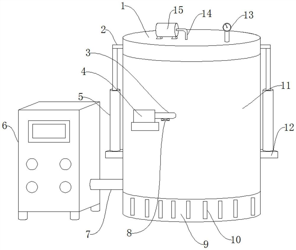
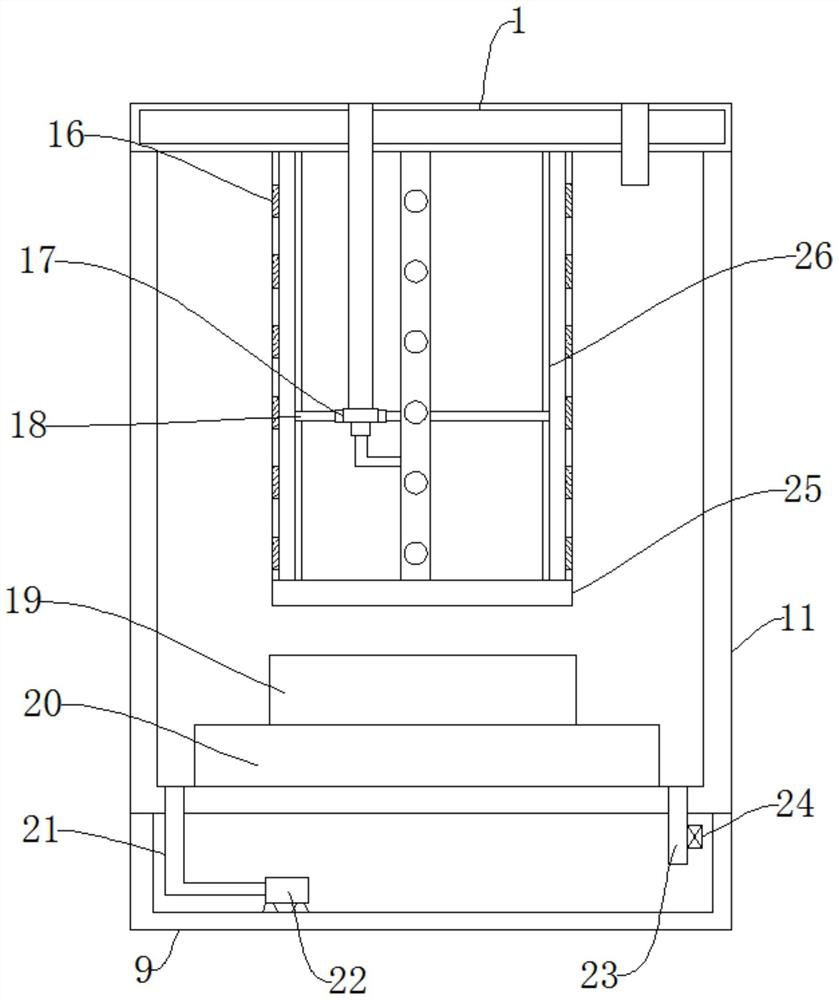
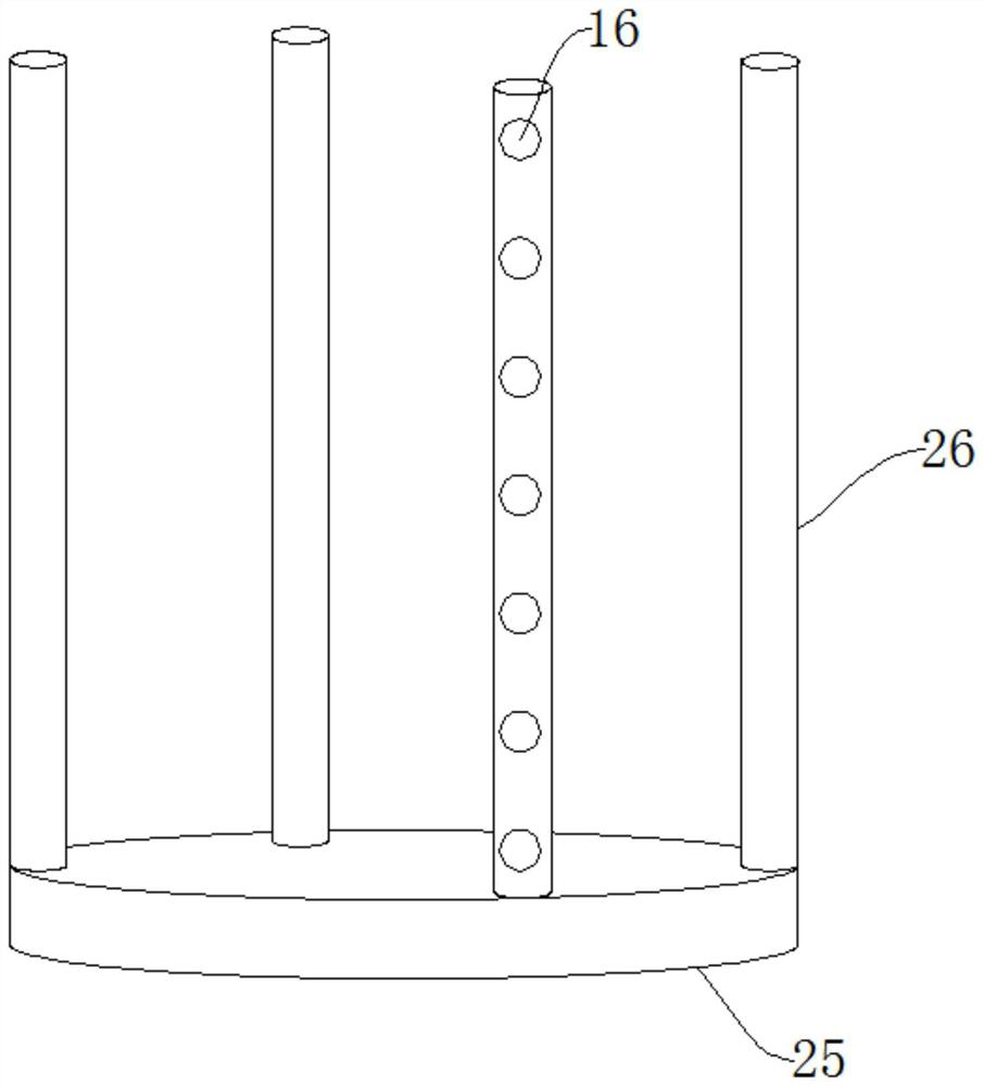
[0034] Such as Figure 1-Figure 4As shown, the coating processing equipment for steel plates includes a base 9, a vacuum tank 11, a tank cover 1 and a hydraulic rod 5, the upper end of the base 9 is provided with the vacuum tank 11, and the upper end of the vacuum tank 11 is provided with the tank cover 1. A bearing plate 12 is fixed on both side walls of the vacuum tank 11, the hydraulic rod 5 is installed on the upper end of the bearing plate 12, the connecting rod 2 is fixed on the top end of the hydraulic rod 5, and the inner wall of the tank cover 1 A fixed rod 26 is arranged on the top, the bottom end of the fixed rod 26 is provided with a bottom plate 25, a vacuum pump-15 is installed on the upper end of the tank cover 1, a vacuum tube-14 is connected to the vacuum pump-15, and one end of the vacuum tube-14 is connected to There is a four-way valve 17, the four-way ...


PUM


Abstract

The steel plate coating machining equipment comprises a base, a vacuum tank, a tank cover and a hydraulic rod, the vacuum tank is arranged at the upper end of the base, the tank cover is arranged at the upper end of the vacuum tank, bearing plates are fixed to the two side walls of the vacuum tank, the hydraulic rod is installed at the upper ends of the bearing plates, and the hydraulic rod is connected with the vacuum tank. A connecting rod is fixed to the top end of the hydraulic rod, a fixing rod is arranged on the inner wall of the tank cover, and a bottom plate is arranged at the bottom end of the fixing rod. The steel plate fixing device has the beneficial effects that by arranging the first vacuum pump, the first vacuum pipe, the four-way valve, the flow dividing pipe and the adsorption holes, in the steel plate fixing process, suction force generated by the first vacuum pump automatically adsorbs and fixes a steel plate through the first vacuum pipe, the four-way valve, the flow dividing pipe and the adsorption holes, manual binding is not needed, the fixing process is simple, and time is saved; and the working intensity of workers is reduced, the fixing effect of the steel plate is guaranteed, and the practicability of the device is improved.

Description

technical field [0001] The invention relates to the technical field of steel plate coating processing equipment, in particular to steel plate coating processing equipment and a processing method thereof. Background technique [0002] Vacuum coating is a technology that produces thin film materials by physical or chemical methods. In the vacuum chamber, the atoms of the material are separated from the heating source and hit the surface of the object to be plated. In the process of steel plate production, it needs to be coated by vacuum coating equipment. . [0003] The existing steel plate coating processing equipment is used to fix the steel plate on the fixed rod by binding. This method is not only cumbersome and time-consuming, but also increases the work intensity of the staff and reduces the practicality and work efficiency of the device. Secondly, the existing steel plate coating processing equipment needs to use an external crane to lift the tank cover, and the tank c...

Claims


Application Information

Patent Timeline
Patent Type & Authority Applications(China)
IPC IPC(8): C23C14/32C23C14/50C23C14/56C23C14/58
CPCC23C14/50C23C14/56C23C14/5806C23C14/32
Inventor 刘慧丹陈元王洪君袁尧李亚晴
Owner ZHAOQING HONGWANG METAL IND
Learn More