Oil-gas separator with spiral line type inlet runner

A technology of oil and gas separator and inlet flow channel, which is applied in the direction of machine/engine, crankcase ventilation, mechanical equipment, etc. The effect of guaranteeing working performance and working life

Active Publication Date: 2022-05-10
NORTHWESTERN POLYTECHNICAL UNIV
View PDF8 Cites 0 Cited by
  • Summary
  • Abstract
  • Description
  • Claims
  • Application Information

AI Technical Summary

Problems solved by technology

[0006] Aiming at the deficiencies in the prior art, the object of the present invention is to provide an oil-gas separator with a helical inlet flow channel, which solves the problem of low separation efficiency and large lubricating oil loss of the dynamic pressure oil-gas separator in the prior art. The problem

Method used


Image

  • Oil-gas separator with spiral line type inlet runner
  • Oil-gas separator with spiral line type inlet runner
  • Oil-gas separator with spiral line type inlet runner

Examples


Embodiment 1

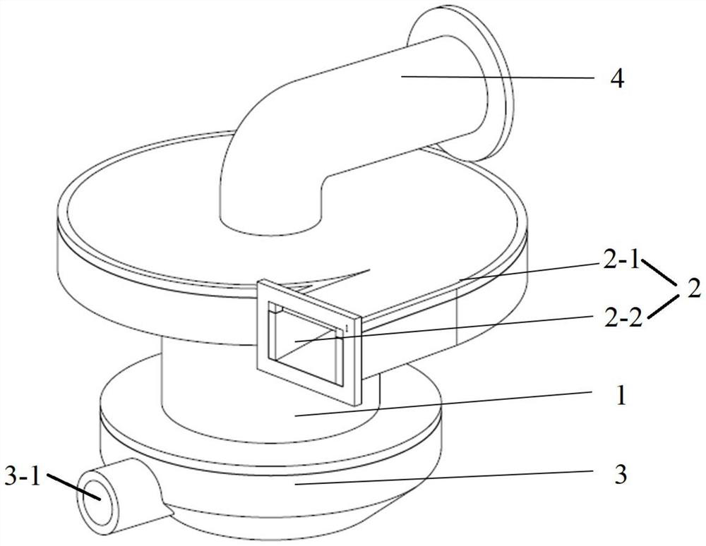
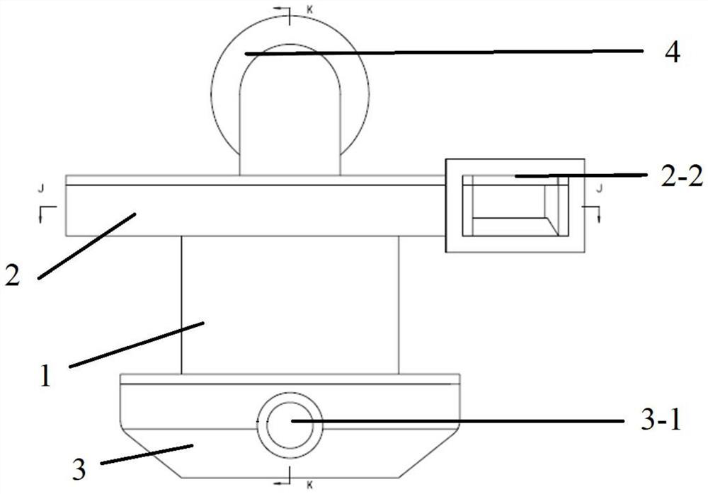
[0044] Comply with the above technical solutions, such as Figure 1 to Figure 8 As shown, an oil-gas separator with a helical inlet channel includes a separation chamber body 1, an oil-gas mixture inlet section 2 and an oil storage chamber 3 connected to both ends of the separation chamber body 1, and an oil-gas mixture inlet section 2 An exhaust pipe 4 is also connected, the exhaust pipe 4 communicates with the separation chamber cylinder body 1, the oil-gas mixture inlet section 3 communicates with the separation chamber cylinder body 1 and the oil storage chamber 3,

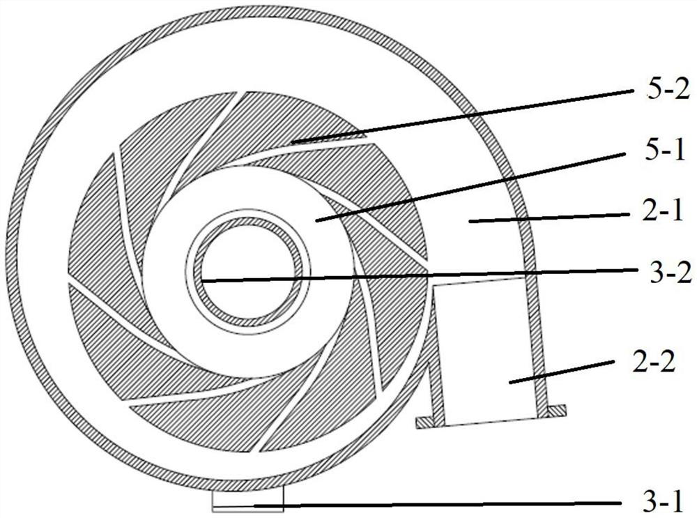
[0045] The oil-gas mixture inlet section 2 includes a pre-swirling flow channel 2-1 and an inlet flow channel 2-2 connected with the pre-swirling flow channel 2-1. The pre-swirling flow channel 2-1 is generally cylindrical in shape, along the An inlet flow channel 2-2 is provided in the tangential direction, and the outer wall of the pre-swirling flow channel 2-1 is an Archimedes spiral; Eight branches, the r...


PUM


Abstract

The oil-gas separator comprises a separation cavity barrel, an oil-gas mixture inlet section and an oil storage cavity, the oil-gas mixture inlet section and the oil storage cavity are connected to the two ends of the separation cavity barrel, an exhaust pipe is further connected to the oil-gas mixture inlet section, and the oil-gas mixture inlet section comprises a pre-swirling flow channel and an inlet flow channel communicated with the pre-swirling flow channel; the pre-swirling flow channel is in a cylinder shape on the whole, an inlet flow channel is arranged in the tangential direction, and the outer side wall of the pre-swirling flow channel is in an Archimedes spiral line shape. According to the dynamic pressure type oil-gas separator, the Archimedes spiral is introduced into the dynamic pressure type oil-gas separator of the aero-engine lubricating oil system, the pre-rotation section above the oil-gas separator is arranged to be of the Archimedes spiral type, and it is guaranteed that the flow of oil-gas mixtures entering all branches is roughly the same; the stability of a flow field in the separator is improved, the lubricating oil amount of a central backflow area of the separator is reduced, and the separation efficiency of the separator is improved.

Description

technical field [0001] The invention relates to the technical field of aero-engine lubricating oil systems, in particular to an oil-gas separator with a helical inlet channel. Background technique [0002] Aeroengines contain a variety of high-speed rotating components, among which high-speed rotating friction components such as bearings and gears bear huge loads. The aero-engine lubricating oil system continuously supplies lubricating oil to these high-speed rotating parts to achieve lubrication and cooling of the frictional contact area, and maintain these parts to work efficiently and continuously. Aeroengine lubricating oil system is mainly composed of fuel tank, fuel supply pump, oil filter, oil return pump, ventilator, oil and gas separator, radiator and other components. Since the lubricating oil system contains a certain amount of air, the lubricating oil in the system will be continuously mixed with the air during the normal operation of the aero-engine to form an ...

Claims


Application Information

Patent Timeline
Patent Type & Authority Applications(China)
IPC IPC(8): F01M13/04
CPCF01M13/04F01M2013/0427Y02T10/12
Inventor 胡剑平刘振侠吕亚国张朝阳李炎军刘振刚高文君朱鹏飞张丽芬吴童
Owner NORTHWESTERN POLYTECHNICAL UNIV
Why Eureka
Try Eureka