Ultrasonic probe clamping rod, ultrasonic detection device and use method of ultrasonic detection device

An ultrasonic probe and clamping rod technology, which is applied to measuring devices, mechanical measuring devices, and uses ultrasonic/sonic/infrasonic waves, etc., can solve the problems of cumbersome on-machine thickness measurement and the inability of clamping rods to be used universally. range, improve the accuracy of ultrasonic measurement, and expand the effect of the measurement range

Active Publication Date: 2022-05-10
CHENGDU AIRCRAFT INDUSTRY GROUP
View PDF5 Cites 0 Cited by
  • Summary
  • Abstract
  • Description
  • Claims
  • Application Information

AI Technical Summary

Problems solved by technology

[0008] The purpose of the present invention is to: in view of existing structures such as deep cavities and ribs in the prior art, it is necessary to measure the thickness from different directions, and between the clamping rods It cannot be used universally, which leads to the need to replace the clamping rod during the machine testing process, resulting in the cumbersome problem of the on-machine thickness measurement process. An ultrasonic probe clamping rod, ultrasonic testing device and its use method are provided

Method used


Image

  • Ultrasonic probe clamping rod, ultrasonic detection device and use method of ultrasonic detection device
  • Ultrasonic probe clamping rod, ultrasonic detection device and use method of ultrasonic detection device
  • Ultrasonic probe clamping rod, ultrasonic detection device and use method of ultrasonic detection device

Examples


Embodiment 1

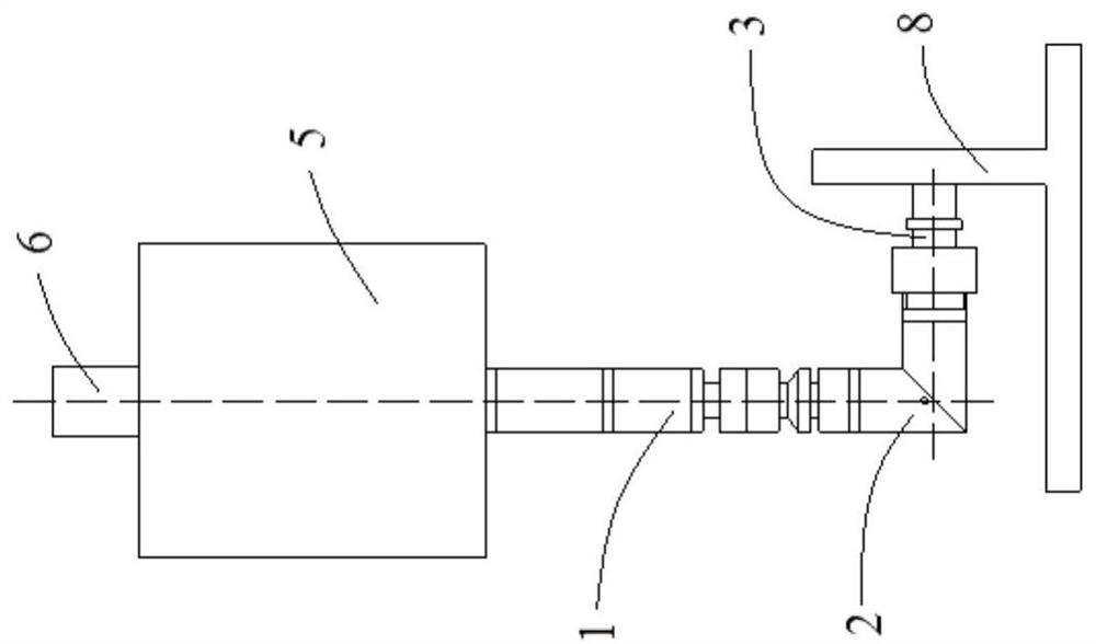
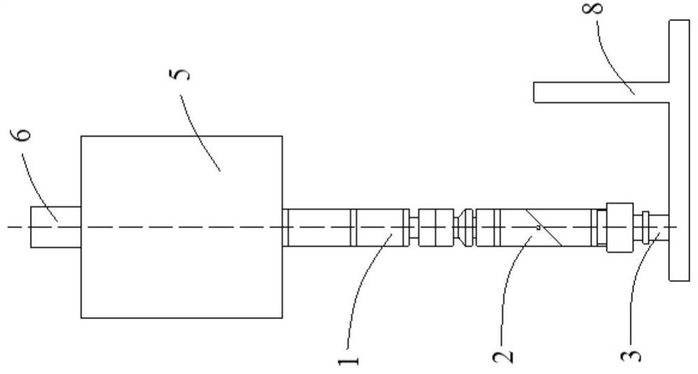
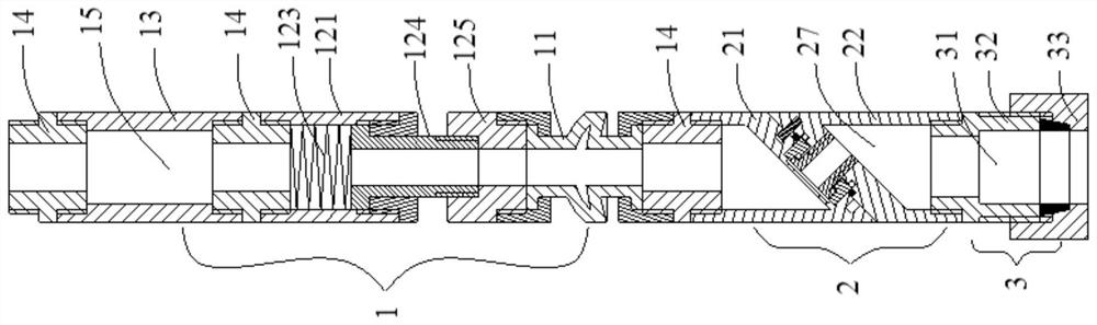
[0064] An ultrasonic probe clamping rod. The ultrasonic probe clamping rod is spliced ​​by a plurality of functional modules in different orders according to the needs of use. The functional modules include a rotatable indexing module 2 and a clamping module for clamping the ultrasonic probe 4. 3. The telescopic module 12 whose length can be changed, the angle deflection module 11 that can be deflected, the connection module 14 for connection, and the extension module 13 for increasing the length of the ultrasonic probe clamping rod, etc. Such as figure 1 and figure 2 As shown, it includes an indexing module 2, a clamping module 3 and a straight rod part 1 spliced ​​by other above-mentioned modules. Such as image 3 As shown, the straight rod part 1 is provided with a first through hole 15 along its axis direction, the indexing module 2 is provided with a second through hole 27 along its axis direction, and the clamping module 3 is provided with a third through hole 27 alon...

Embodiment 2

[0074] An ultrasonic probe clamping rod, the difference from the technical solution in Embodiment 1 is that the straight rod part 1 in this embodiment includes an angle deflection module 11, and the angle deflection module 11 is provided with a fourth through hole along its own axis 113 . In this embodiment, the fourth through hole 113 is a component of the first through hole 15 .

[0075] Such as Figure 12 As shown, the two ends of the angle deflection module 11 are connection parts 111, the connection part 111 is a tubular structure, a fifth flange 1111 is provided on the inner side of one end of the connection part 111, and the surface of the connection part 111 is provided with threads for connecting with other structures. A deformation piece is provided between the two connecting parts 111, and a sixth flange 1123 and a seventh flange 1124 are provided on the deformation piece. After the angle deflection module 11 is connected with other structures, the sixth flange 1123...

Embodiment 3

[0079] An ultrasonic probe clamping rod. The difference from the solutions disclosed in Embodiment 1 and Embodiment 2 is that the straight rod part 1 in this embodiment also includes a telescopic module 12 that can expand and contract. The telescopic module 12 is provided with The fifth through hole 126 in the axial direction, in this embodiment, the fifth through hole 126 is a component of the first through hole 15 . Such as Figure 13 As shown, the telescopic module 12 includes a telescopic cavity 121 and a telescopic column 124, the upper end of the telescopic cavity 121 and the lower end of the telescopic column 124 are provided with a structure for connecting with other structures of the straight rod part 1, such as the connection structure at the lower end of the telescopic column 124 1242 is thread.

[0080]The inner lower end of the telescopic chamber 121 is provided with a third flange 122, the upper end of the telescopic column 124 is provided with a hanging platfor...


PUM


Abstract

The invention relates to the field of numerical control machining detection, in particular to an ultrasonic probe clamping rod, an ultrasonic detection device and a use method of the ultrasonic detection device. The ultrasonic probe clamping rod comprises a straight rod part, a transposition module and a clamping module, the transposition module comprises a first rotating part and a second rotating part which are rotationally connected, the first rotating part is detachably connected with one end of the straight rod part, and the second rotating part is detachably connected with the clamping module; the axis of the straight rod part is parallel to the axis of the first rotating part; the transposition module comprises a flat angle station and a right angle station, station switching of the transposition module is achieved through rotation of the first rotating component relative to the second rotating component, when the transposition module is located at the flat angle station, the axis of the first rotating component is parallel to the axis of the second rotating component, and when the transposition module is located at the right angle station, the axis of the second rotating component is parallel to the axis of the first rotating component. The axis of the first rotating component is perpendicular to the axis of the second rotating component. The ultrasonic probe clamping rod has universality and can be used for measuring the thicknesses of different structures on parts.

Description

technical field [0001] The invention relates to a clamping device, in particular to an ultrasonic probe clamping rod, an ultrasonic detection device and a use method thereof. Background technique [0002] As an important field of the current manufacturing industry, CNC machining has an extremely important impact on the quality of its products on the development of the national equipment manufacturing industry. For the quality inspection methods before and after processing of parts, various mature technologies have been developed, such as ultrasonic flaw detection, hardness test, three-coordinate measuring machine detection and other methods. However, the quality control method in the process of parts processing lacks relatively mature technology at present. [0003] The process of detecting parts during the processing of parts on the machine tool is on-machine inspection, which can be divided into manual and automatic methods. The manual method mainly uses manual measureme...

Claims


Application Information

Patent Timeline
Patent Type & Authority Applications(China)
IPC IPC(8): G01B17/02
CPCG01B17/02G01B5/0002Y02E30/30
Inventor 刘宇阳曾阳刘大炜郭瑞华岳玉亮代良强
Owner CHENGDU AIRCRAFT INDUSTRY GROUP
Why Eureka
Try Eureka