

Purification device suitable for industrial oil fume purification
A purification device and oil fume purification technology, applied in the field of oil fume purification, can solve the problems of uneven electric field distribution and inability to achieve online cleaning, and achieve the effects of uniform distribution, reduced space occupied, and high cleaning efficiency
- Summary
- Abstract
- Description
- Claims
- Application Information
AI Technical Summary
Problems solved by technology
Method used
Image


Examples
Embodiment 1
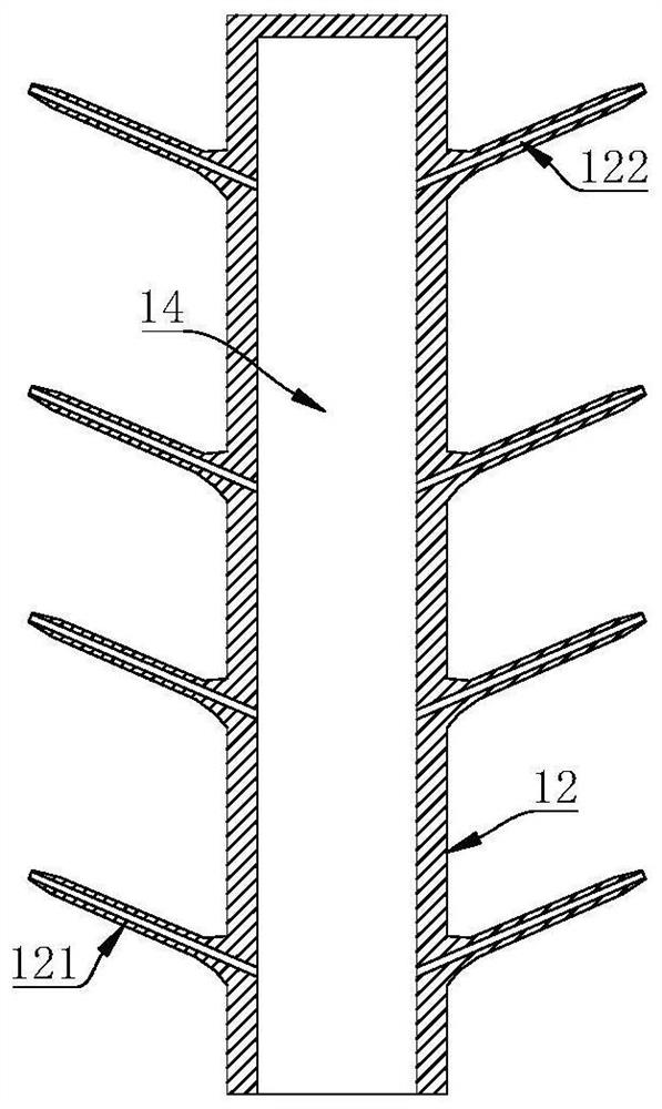
[0037] refer to Figure 1 to Figure 6, a purification device suitable for industrial oil fume purification, comprising a honeycomb purification electric field 1, the honeycomb purification electric field 1 includes a plurality of uniformly distributed cathode adsorption tubes 11, and an anode tube 12 is arranged in the cathode adsorption tubes 11, A purification channel 13 is formed between the cathode adsorption tube 11 and the anode tube 12, a cleaning channel 14 is arranged in the anode tube 12, and a discharge discharge port extending into the purification channel 13 is also provided on the anode tube 12. Needle 121 , the discharge needle 121 is provided with a liquid spray chamber 122 for spraying cleaning liquid into the purification channel 13 , and the purification channel 13 communicates with the cleaning channel 14 through the liquid spray chamber 122 .
[0038] The cleaning liquid can be stored in the box body, and a pump body is arranged on the box body. The cleani...
Embodiment 2
[0040] refer to Figure 1 to Figure 6 , in order to reduce the volume of the honeycomb purification electric field 1 and improve the cleaning efficiency of the honeycomb purification electric field 1, on the basis of the above embodiment: the cross-sectional shape of the purification channel 13 is a regular hexagon, and the cathode adsorption tube 11 It includes side walls forming the purification channel 13 , and each of the side walls corresponds to at least two discharge needles 121 .
[0041] The cleaning channel 13 is arranged vertically, the discharge needle 121 is arranged obliquely, and the cleaning liquid sprayed from the liquid spray chamber 122 is sprayed onto the side wall from bottom to top.
[0042] The included angle between the discharge needle 121 and the axis of the anode tube 12 is 30° to 60°.
[0043] The discharge needle 121 includes a needle body 123 and a needle seat 124 integrated with the needle body 123 , the diameter of the needle seat 124 is larger...
Embodiment 3
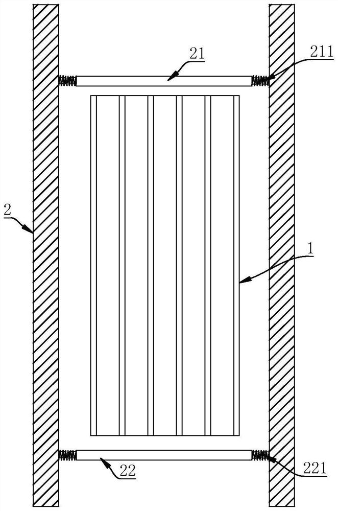
[0046] refer to Figure 1 to Figure 6 , in order to improve the cleaning efficiency of the honeycomb purification electric field 1, on the basis of the above embodiment: the purification device also includes a support frame 2, the honeycomb purification electric field 1 is installed in the support frame 2, and the support frame 2, an upper ultrasonic generator 21 is installed above the honeycomb-shaped purification electric field 1, and the upper ultrasonic generator 21 is fixed on the support frame 2 by an upper spring 211.
[0047] The support frame 2 is provided with an upper positioning column for fixing the upper spring 211, the upper ultrasonic generator 21 is provided with a first positioning column, and one end of the upper spring 211 is sleeved on the upper positioning column, The other end of the upper spring 211 is sleeved on the first positioning post.
[0048] The purification device also includes a support frame 2, the honeycomb purification electric field 1 is ...
PUM
 Abstract
Description
Claims
Application Information