Rotary welding gun
A technology of spin welding and welding device, used in welding equipment, auxiliary welding equipment, welding/cutting auxiliary equipment, etc., can solve the problems of troublesome replacement of welding guns, low degree of freedom, low welding efficiency, etc., to improve welding efficiency and welding efficiency. High, convenient and fast welding effect
- Summary
- Abstract
- Description
- Claims
- Application Information
AI Technical Summary
Problems solved by technology
Method used
Image

Examples
Embodiment 1
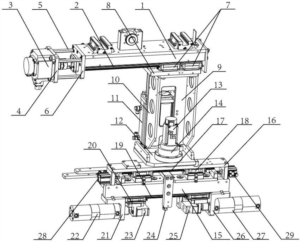
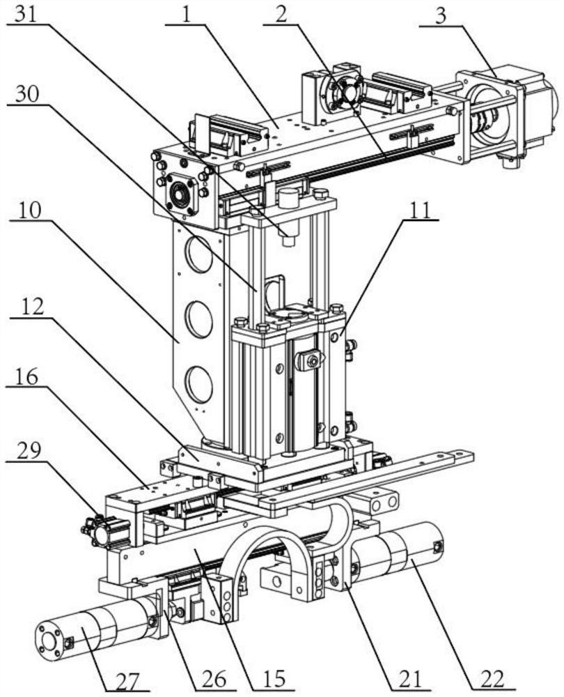
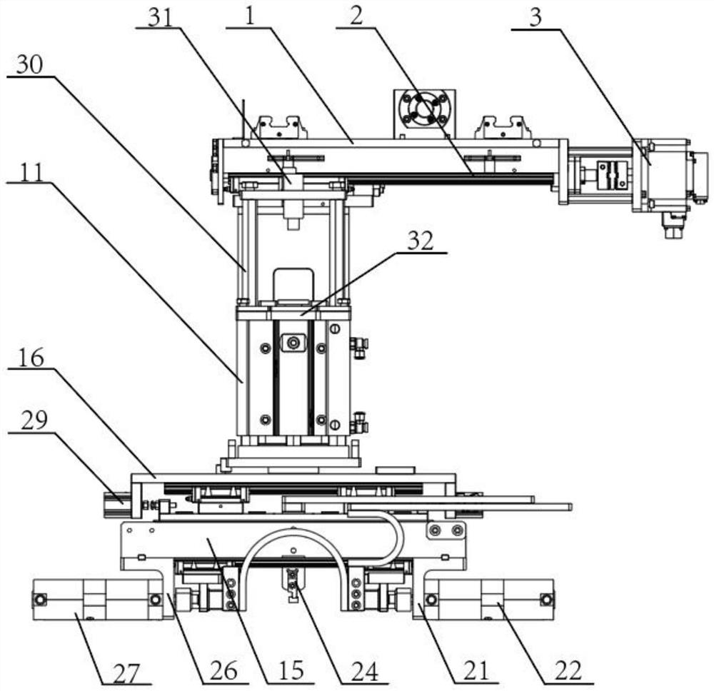
[0038] figure 1 It is a schematic diagram of the three-dimensional structure of the present invention, figure 2 It is a schematic diagram of the rear view stereoscopic structure of the present invention, image 3 It is a schematic diagram of the rear view structure of the present invention, such as figure 1 , figure 2 and image 3 A rotary welding torch is shown, comprising: a welding device, a translation device and a lifting device, the welding device is connected to the lower end of the lifting device, the translation device is connected to the upper end of the lifting device, and a rotating device is installed at the connection between the lifting device and the welding device , the translation device includes a drive base A1 and a servo motor A3, the servo motor A3 is connected to one end of the drive base A1, a guide rail A2 is connected to the lower end of the drive base A1, and the lifting device and the guide rail A2 are slidingly connected to each other. The li...
Embodiment 2
[0040] figure 1 It is a schematic diagram of the three-dimensional structure of the present invention, figure 2 It is a schematic diagram of the rear view stereoscopic structure of the present invention, image 3 It is a schematic diagram of the rear view structure of the present invention, such as figure 1 , figure 2 and image 3 A kind of rotary welding torch shown comprises: driving device, lifting device and welding device, the present invention is fixedly connected with connecting bracket 16 on the upper end of welding bracket 15, and described driving mechanism includes floating cylinder A28, floating cylinder B29, welding plus Pressing cylinder A22 and welding pressurizing cylinder B27, floating cylinder A28 and floating cylinder B29 are respectively installed on the left and right sides of connecting bracket 16, and welding pressurizing cylinder A22 and welding pressurizing cylinder B27 are all connected to the lower end of welding support 15, welding and adding ...
Embodiment 3
[0042] figure 1 It is a schematic diagram of the three-dimensional structure of the present invention, figure 2 It is a schematic diagram of the rear view stereoscopic structure of the present invention, image 3 It is a schematic diagram of the rear view structure of the present invention, such as figure 1 , figure 2 and image 3 The shown rotary welding torch includes: a driving device, a lifting device and a welding device. In the present invention, a guide rail B17 is connected to the lower end of the connecting bracket 16, and the welding bracket 15 and the guide rail B17 slide mutually through two sliders B18. connection, the lower end of the welding bracket 15 is connected with a guide rail C19, and the welding electrode A23 and the welding electrode C25 are respectively slidingly connected between two sliders C20 and the guide rail C19, and one end of the driving seat A1 is connected with a motor fixing frame. The motor fixing frame is composed of a fixed plate A...
PUM
 Abstract
Description
Claims
Application Information
 - R&D
- Intellectual Property
- Life Sciences
- Materials
- Tech Scout
- Unparalleled Data Quality
- Higher Quality Content
- 60% Fewer Hallucinations
Browse by: Latest US Patents, China's latest patents, Technical Efficacy Thesaurus, Application Domain, Technology Topic, Popular Technical Reports.
© 2025 PatSnap. All rights reserved.Legal|Privacy policy|Modern Slavery Act Transparency Statement|Sitemap|About US| Contact US: help@patsnap.com