Supercharge Your Innovation With Domain-Expert AI Agents!

Dismounting device for walking motor and speed reducer of stacking machine

A technology for traveling motors and dismantling devices, which is applied in metal processing equipment, metal processing, manufacturing tools, etc., and can solve problems such as stacker power, different shapes, damaged and deformed shelves, stacker travel motors and reducer fall, etc. problems, to achieve the effect of eliminating falling from high altitude and dumping and hurting people, saving the workload of handling, and moving flexibly and conveniently

Pending Publication Date: 2022-05-13
CHINA TOBACCO SHAANXI IND
View PDF1 Cites 0 Cited by
  • Summary
  • Abstract
  • Description
  • Claims
  • Application Information

AI Technical Summary

Problems solved by technology

However, in the actual use process, due to the heavy weight of the travel motor and the reducer, the pulley block will generate a very large external force when the travel motor and the reducer move on the horizontal slide bar, causing the horizontal slide bar to move. After the slide bar moves There will be potential safety hazards of the stacker walking motor and reducer falling and hurting people; at the same time, the slide bar is erected horizontally on the shelf, but the high-bay warehouse shelf has technical requirements for load. Exceeding the load requirement will cause the shelf to be damaged and deformed. Serious safety accidents will occur after raw materials, tobacco materials, finished cigarettes and other materials are placed on the shelves
In addition, because tobacco industry enterprises will build multiple high-bay warehouses for raw materials, tobacco materials, and finished products, the power and shape of stackers in different high-bay warehouses are different. Design and manufacture a disassembly device, causing unnecessary waste

Method used


Image

  • Dismounting device for walking motor and speed reducer of stacking machine
  • Dismounting device for walking motor and speed reducer of stacking machine
  • Dismounting device for walking motor and speed reducer of stacking machine

Examples


Embodiment Construction

[0018] The following will clearly and completely describe the technical solutions in the embodiments of the present invention with reference to the accompanying drawings in the embodiments of the present invention. Obviously, the described embodiments are only some, not all, embodiments of the present invention. Based on the embodiments of the present invention, all other embodiments obtained by persons of ordinary skill in the art without making creative efforts belong to the protection scope of the present invention.

[0019] It should be noted that, in this document, the terms "comprising", "comprising" or any other variation thereof are intended to cover a non-exclusive inclusion such that a process, method, article or apparatus comprising a set of elements includes not only those elements, It also includes other elements not expressly listed, or elements inherent in the process, method, article, or apparatus. without further restrictions. An element defined by the phrase...


PUM


Abstract

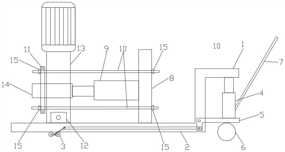
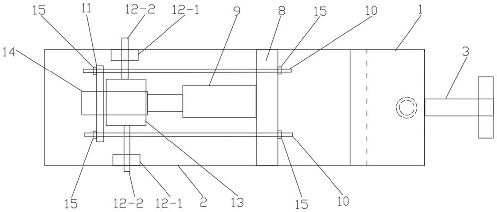
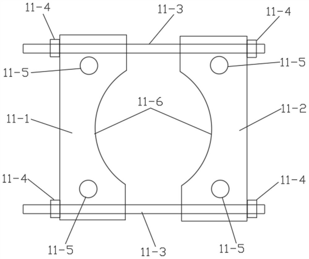
The dismounting device comprises a manual pallet fork, the manual pallet fork comprises a pallet fork body, a supporting seat is vertically and fixedly arranged on the upper portion of the rear end of the pallet fork body, and a chuck used for pulling the walking motor and the speed reducer of the stacking machine is arranged on the upper portion of the front end of the pallet fork body. The upper side and the lower side of the supporting seat are fixedly connected with the chuck through connecting rods I. A pushing hydraulic cylinder used for abutting against a stacker walking motor shaft is fixedly arranged in the middle of the front side face of the supporting seat, and motor fixers used for abutting against and fixing the lower portions of the two sides of a stacker walking motor and a speed reducer are arranged on the two sides of the front end of the pallet fork body. The dismounting efficiency of the walking motor and the speed reducer of the stacker is improved, the maintenance workload of workers is reduced, the maintenance time of the stacker is shortened, and the safety risk that the motor and the speed reducer of the stacker fall and fall to hurt people is reduced.

Description

technical field [0001] The invention belongs to the technical field of motor disassembly, and in particular relates to a disassembly device for a travel motor and a reducer of a stacker. Background technique [0002] Tobacco industry enterprises have elevated warehouses for raw materials, tobacco materials, and finished products. Stackers are installed in the elevated warehouses for raw materials, tobacco materials, finished cigarettes, and other materials to go out and into the elevated warehouses. In order to ensure the normal load of the stackers In operation, the power and weight of the travel motor and reducer configured by the stacker are large, and the total weight of the travel motor and reducer is generally several hundred kilograms. When the travel wheel, travel bearing, travel motor and other equipment of the stacker break down, it is necessary to disassemble the travel motor and reducer for maintenance. Since there is no special disassembly tool, and the travel m...

Claims


Application Information

Patent Timeline
IPC IPC(8): B23P19/027B23P19/00
CPCB23P19/027B23P19/00
Inventor 姜华田虎明林江栾博薛盛鑫郭伟刘浩旭朱军康娟娟郭俹瑃刘健薛峰苗航
Owner CHINA TOBACCO SHAANXI IND
Features
  • R&D
  • Intellectual Property
  • Life Sciences
  • Materials
  • Tech Scout
  • Unparalleled Data Quality
  • Higher Quality Content
  • 60% Fewer Hallucinations
Learn More