Automatic grinding and polishing machine

A polishing machine and rotating column technology, applied in the field of parts polishing, can solve the problems of cumbersome operation, slowing down polishing efficiency, metal dust human injury, etc., to reduce polishing difficulty, facilitate cleaning and collection, and improve polishing efficiency.

Inactive Publication Date: 2022-05-13
徐州大业三维科技有限公司
View PDF0 Cites 2 Cited by
  • Summary
  • Abstract
  • Description
  • Claims
  • Application Information

AI Technical Summary

Problems solved by technology

[0002] In order to reduce the roughness of the surface of auto parts and improve the quality of auto parts during the processing of auto parts, polishing machines are often used to polish and polish auto parts. The working steps are to drive the sponge or wool installed on the polishing machine through the motor The polishing disc rotates at a high speed. Due to the joint action of the polishing disc and the polishing agent and friction with the surface to be polished, the purpose of removing surface pollution, oxide layer and shallow marks can be achieved; existing auto parts such as Figure 9 As shown, this part is mainly used on automobile radiators, and the through holes for positioning or installation on this part are more cumbersome to operate when grinding and polishing.
[0003] The following problems often exist in the existing grinding of through holes on auto parts: a: When grinding the through holes on the surface of auto parts, it is necessary to manually grind the two sides of the through holes and the inner wall of the through holes, and the manual grinding is difficult. High, which slows down the grinding efficiency; b: Existing auto parts are prone to produce metal dust when they are polished, and the metal powder is easy to be sucked into the human respiratory tract and cause damage to the human body, and the waste generated by grinding Difficult to clean up

Method used


Image

  • Automatic grinding and polishing machine
  • Automatic grinding and polishing machine
  • Automatic grinding and polishing machine

Examples


Embodiment Construction

[0027] The following will clearly and completely describe the technical solutions in the embodiments of the present invention with reference to the accompanying drawings in the embodiments of the present invention. Obviously, the described embodiments are only some, not all, embodiments of the present invention. Based on the embodiments of the present invention, all other embodiments obtained by persons of ordinary skill in the art without making creative efforts belong to the protection scope of the present invention.

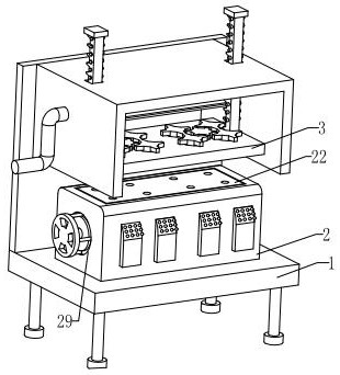
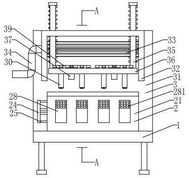
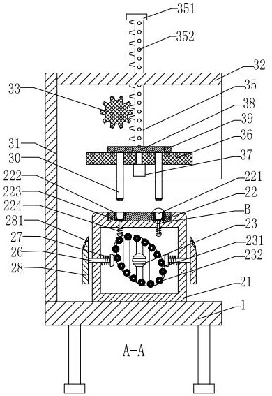
[0028] refer to Figure 1-Figure 9 , an automatic grinding and polishing machine, comprising a support base 1, a fixing component 2 and a polishing component 3, the fixing component 2 is fixedly installed in the middle of the upper end surface of the support base 1, a polishing component 3 is arranged above the fixing component 2, and the polishing component 3 is fixed Installed on the support base 1.

[0029] refer to Figure 1-Figure 3, the fixed assembly ...


PUM


Abstract

The automatic grinding and polishing machine comprises a supporting base, a fixing assembly and a polishing assembly, the fixing assembly is fixedly installed above the upper end face of the supporting base, the polishing assembly is arranged above the fixing assembly, and the polishing assembly is fixedly installed on the supporting base; the problems that when automobile parts are polished, the two sides and the inner wall of a through hole need to be manually polished when the through hole in the surface of the automobile parts is polished at present, the manual polishing difficulty is high, and the polishing efficiency is lowered are solved; and b, when existing automobile parts are subjected to polishing treatment, metal powder scraps are easily generated, the metal powder scraps are easily sucked into the respiratory tract of a human body so as to injure the human body, and waste scraps generated by polishing are difficult to clean.

Description

technical field [0001] The invention relates to the technical field of parts grinding, in particular to an automatic grinding and polishing machine. Background technique [0002] In order to reduce the roughness of the surface of auto parts and improve the quality of auto parts during the processing of auto parts, polishing machines are often used to polish and polish auto parts. The working steps are to drive the sponge or wool installed on the polishing machine through the motor The polishing disc rotates at a high speed. Due to the joint action of the polishing disc and the polishing agent and friction with the surface to be polished, the purpose of removing surface pollution, oxide layer and shallow marks can be achieved; existing auto parts such as Figure 9 As shown, the part is mainly used on the radiator of the automobile, and the through holes for positioning or installation provided on the part are polished and polished, and the operation is relatively cumbersome. ...

Claims


Application Information

Patent Timeline
Patent Type & Authority Applications(China)
IPC IPC(8): B24B27/00B24B27/033B24B5/48B24B5/35B24B41/06B24B47/00B24B41/04B24B47/12B24B47/22B24B55/06B24B55/12B24B41/02
CPCB24B27/0076B24B27/033B24B5/48B24B5/35B24B41/06B24B47/00B24B41/04B24B47/12B24B47/22B24B55/06B24B55/12B24B41/02
Inventor 陈烜
Owner 徐州大业三维科技有限公司
Why Eureka
Try Eureka