Construction tool and construction method for rapid in-place and replacement of large transformer

A construction method and technology for transformers, which are applied in inductance/transformer/magnet manufacturing, switchgear, electrical components, etc., can solve the problems of long construction time, high-altitude work, and low installation accuracy for large transformers, and improve equipment installation efficiency. , save the work, easy to operate and safe effect

Pending Publication Date: 2022-05-13
MCC5 GROUP CORP SHANGHAI
View PDF1 Cites 0 Cited by
  • Summary
  • Abstract
  • Description
  • Claims
  • Application Information

AI Technical Summary

Problems solved by technology

[0005] Due to the above-mentioned defects in the prior art, the present invention provides a construction tool and construction method for large-scale transformer installation to solve the problems of long installation and construction time of large-scale transformers, low installation accuracy, large amount of high-altitude operations, and low installation efficiency.

Method used


Image

  • Construction tool and construction method for rapid in-place and replacement of large transformer
  • Construction tool and construction method for rapid in-place and replacement of large transformer
  • Construction tool and construction method for rapid in-place and replacement of large transformer

Examples


Embodiment 1

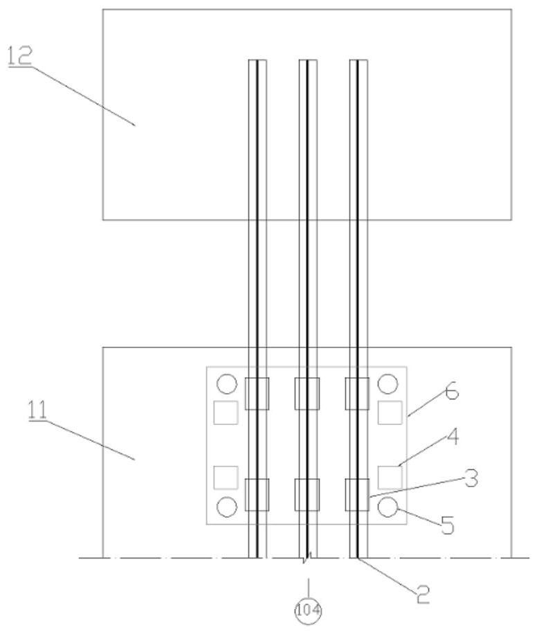
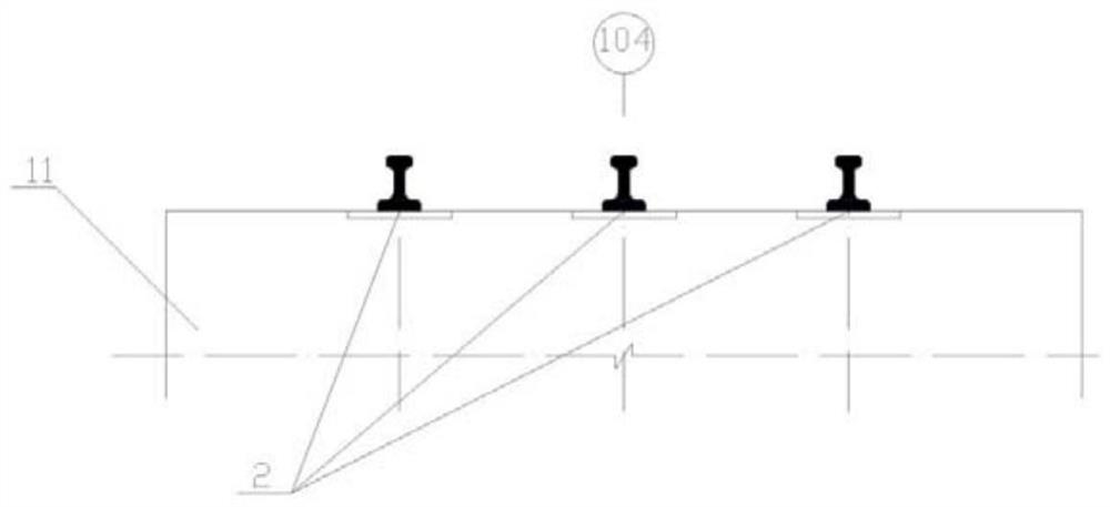
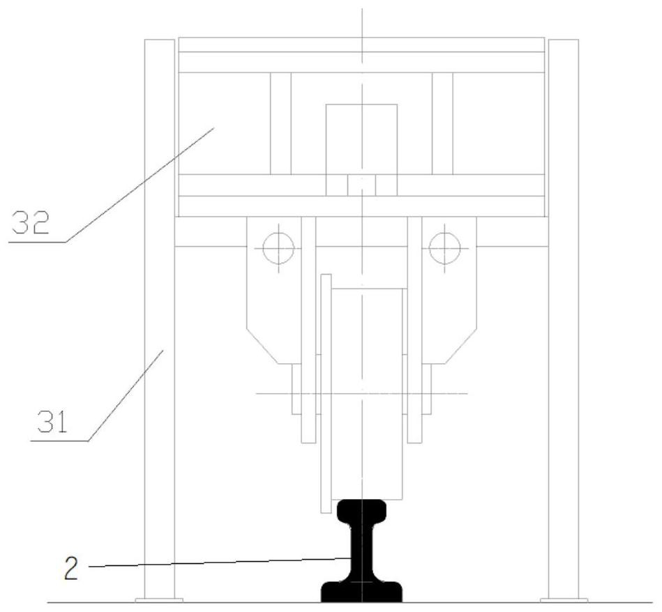
[0047] Such as figure 1 As shown, a construction tool for large-scale transformer installation includes a permanent track 2, a rolling device 3, a transformer positioning tool 4 and a transformer lifting tool 5; the track 2 is fixed on the construction floor and extends from the transformer assembly station 11 to the transformer installation station 12. Such as figure 2 As shown, track 2 is three parallel QU70 track steels. The transformer positioning tool 4 and the transformer lifting tool 5 are detachable. Such as image 3 As shown, the rolling bearing 32 of the rolling device is connected above the track 2 . Two rolling bearings 32 and rolling bearing positioning tooling 31 are arranged on any one track. The rolling bearing positioning tooling 31 includes angle steel and support plates. The selected angle steel specification is L45*5mm, and the support plate is a 5mm thick steel plate. Such as Figure 4 As shown, the transformer positioning tool 4 includes H-shaped...

Embodiment 2

[0057] The construction of a large-scale transformer replacement using the construction tooling in Implementation 1 includes the following steps:

[0058] Step S1, using the track 2 to hoist the transformer 6 from the transformer installation station 12 to the assembly station 11;

[0059] Step S2, using the transformer lifting tooling 5 to lift the transformer and the rolling support off the track 2 as a whole;

[0060] Step S3, the transformer body 6 is disengaged from the rolling bearing 32;

[0061] Step S4, hoisting and replacing the transformer body;

[0062] Step S5, the replaced transformer is positioned and leveled using the transformer positioning tool 4;

[0063] Step S6, the replaced transformer body is connected to the rolling bearing 32;

[0064] Step S7, use the transformer lifting tooling 5 to lower the replaced transformer and rolling bearing as a whole and place it on the track 2;

[0065] Step S8, hoisting the replaced transformer to the transformer inst...


PUM


Abstract

The invention discloses a construction tool and a construction method for rapid in-place and replacement of a large transformer. On one hand, the construction tool comprises a permanent track, a rolling support, a rolling support positioning tool, a transformer positioning tool and a transformer lifting tool; the permanent transportation track is adopted for rapidly installing the transformer in place, the equipment installation efficiency is improved, later maintenance, overhaul and replacement of the equipment are facilitated, ground assembly of the large transformer can be achieved, high-altitude operation is reduced, and operation is more convenient and safer. And the temporary tool can be made of sporadic materials on site and can be repeatedly used, so that the construction cost is reduced. On the other hand, the construction method comprises an installation method and a replacement method; the screw jack is adopted to place the large transformer on the transportation track in a balanced manner, so that the impact on the transformer walking device caused by direct hoisting of a crane in place is avoided; and the equipment can be hoisted in place by adopting the transformer maintenance workshop working travelling crane, so that the machine team of a large crane is saved.

Description

technical field [0001] The invention relates to the technical field of equipment installation and construction, and more specifically, to a construction tool and construction method for quickly placing and replacing a large transformer. Background technique [0002] Quantum electric furnace is quantum electric arc furnace, which is a new type of smelting equipment, which is used in large iron and steel enterprises to fully automate the steelmaking process. The scrap steel trough of the Quantum Electric Furnace is equipped with a lifting system, siphon type steel-free slag discharge, flexible furnace shell installation, tilting, and replacement methods, and an innovative waste gas treatment system, which can reduce production costs by about 20%. Theoretically, the average smelting cycle of the quantum electric furnace is ≤40min, the power consumption is 280kWh / t, and the electrode consumption is 0.9kg / t, which is 30% shorter than the ordinary electric furnace smelting cycle. ...

Claims


Application Information

Patent Timeline
Patent Type & Authority Applications(China)
IPC IPC(8): H01F41/00H02B3/00
CPCH01F41/00H02B3/00
Inventor 代智肄汪峻峰石勇
Owner MCC5 GROUP CORP SHANGHAI
Why Eureka
Try Eureka