
Formation method of semiconductor structure

A semiconductor and patterning technology, used in semiconductor/solid-state device manufacturing, electrical components, circuits, etc., can solve the problems of uneven key dimensions and poor semiconductor structure performance, and achieve the effect of improving uniformity and performance.

Pending Publication Date: 2022-05-13
SEMICON MFG INT (SHANGHAI) CORP +1
View PDF0 Cites 0 Cited by
  • Summary
  • Abstract
  • Description
  • Claims
  • Application Information

AI Technical Summary

Problems solved by technology

[0004] At present, in the case of continuous shrinking technology nodes, there is a problem of non-uniform critical dimensions of patterns formed by lithography, resulting in poor performance of the formed semiconductor structure

Method used


Image

  • Formation method of semiconductor structure
  • Formation method of semiconductor structure
  • Formation method of semiconductor structure

Examples


Embodiment Construction

[0030] It can be seen from the background art that the size uniformity of the pattern structure formed by the current photolithography and etching process is poor. The reasons for the poor uniformity of the graphics are now analyzed in conjunction with the specific drawings.

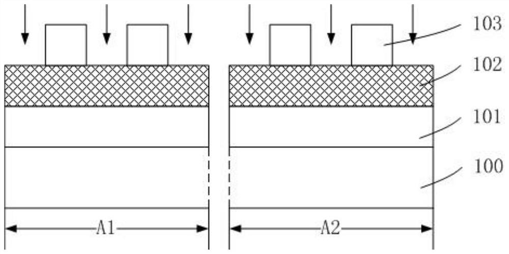
[0031] refer to figure 1 , provide a wafer 100, and the wafer 100 includes several chip regions.

[0032] In a specific embodiment, the wafer 100 located in the chip area can form various semiconductor components, such as various appropriate transistors, memories, field effect transistors, and the like.

[0033] For the convenience of subsequent description, in the semiconductor formation process of this embodiment, two of the chip areas are taken as an example for illustration, including the first chip area A1 and the second chip area A2.

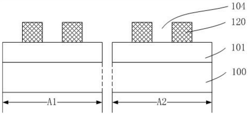
[0034] refer to figure 2 A layer to be etched 101 and a sacrificial material layer 102 are sequentially formed on the wafer 100 in the chip region; a first patt...


PUM


Abstract

A semiconductor structure forming method comprises the steps that a current wafer is provided, the current wafer comprises a plurality of chip areas, a to-be-etched layer and a core mold structure are sequentially formed on the current wafer, the core mold structure comprises a sacrificial layer and covering layers, and the thicknesses of the covering layers of the chip areas are different; forming a side wall on the side wall of the core mold structure; etching a part of the covering layer and a part of the sacrificial layer until the surface of the to-be-etched layer is exposed, and forming a first opening in the residual core mold structure; obtaining the etching rate of the sacrificial layer of each chip area of the current wafer and feeding back the etching rate to the control system, wherein the etching rates of the sacrificial layers of the chip areas are different; and the control system adjusts the thickness of the covering layer formed on the next wafer according to the etching rate of the sacrificial layer, and the thickness of the covering layer formed on the next wafer is sequentially increased along with the increase of the etching rate of the sacrificial layer. The forming method of the semiconductor structure provided by the embodiment of the invention is beneficial to improving the uniformity of the pattern size and improving the performance of the semiconductor structure.

Description

technical field [0001] The invention relates to the technical field of semiconductor manufacturing, in particular to a method for forming a semiconductor structure. Background technique [0002] Semiconductor manufacturing technology requires a variety of different physical and chemical processes on semiconductor wafers, and photolithography is one of the most important processes in semiconductor manufacturing technology. The photolithography process is the main process of removing a specific part of the wafer surface film through a series of production steps. Through photolithography and etching, a film with a pattern structure can be formed on the wafer surface. [0003] With the rapid growth of semiconductor technology, driven by Moore's Law, semiconductor technology continues to move towards smaller process nodes, making semiconductors develop in the direction of smaller volume, higher circuit precision, and higher circuit complexity. With the continuous shrinking of th...

Claims


Application Information

Patent Timeline
IPC IPC(8): H01L21/308
CPCH01L21/3086H01L21/3085
Inventor 刘睿姚笛
Owner SEMICON MFG INT (SHANGHAI) CORP
Learn More