Digital television cathode ray tube screen display dead pixel detection method

A cathode ray tube and digital TV technology, which is applied in TV, electrical components, image communication, etc., can solve the problems of not providing detection of concave spots outside the screen, single detection method of screen dead spots, and failure to find black spots, etc., to achieve increased The effect of the range of use, convenience for pixel failure, and simple structure

Pending Publication Date: 2022-05-13
冯阳
View PDF0 Cites 0 Cited by
  • Summary
  • Abstract
  • Description
  • Claims
  • Application Information

AI Technical Summary

Problems solved by technology

[0004] Existing detection methods for dead pixels on digital TV screens are too simple, and can only detect pixels, that is, the dead pixels of cathode ray tubes. However, in the process of screen production, if the outer wall of the screen is squeezed, a small Concavity, this depression point will also produce black spots with reduced brightness during detection, but the existing detection device does not provide the function of detecting concave points outside the screen, so that the staff cannot find the specific reason for the formation of a certain black point

Method used


Image

  • Digital television cathode ray tube screen display dead pixel detection method
  • Digital television cathode ray tube screen display dead pixel detection method
  • Digital television cathode ray tube screen display dead pixel detection method

Examples


Embodiment 1

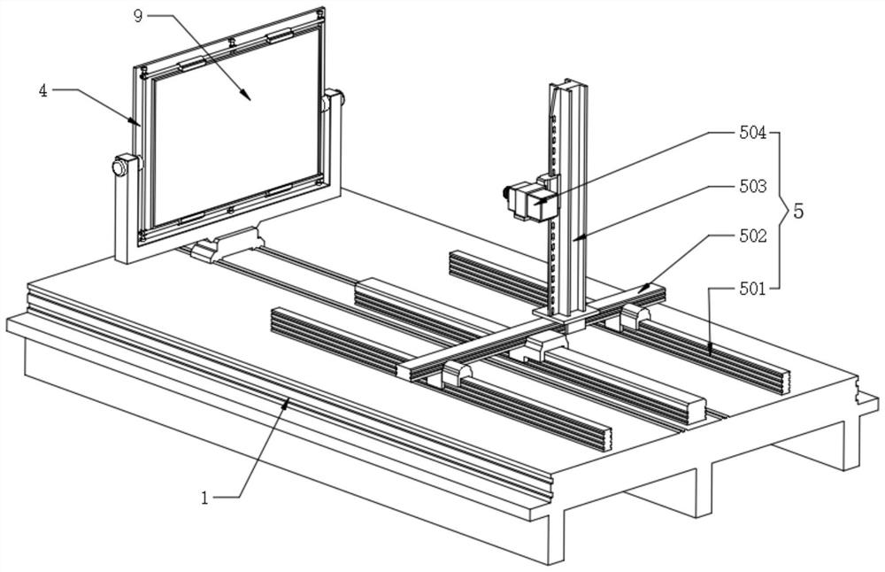
[0059] Refer to attached Figure 4 , the screen holder 4 also includes a base 401, the top of the base 401 is rotatably mounted with a back plate 402, the side wall of the back plate 402 close to the pixel defect detection assembly 5 is equidistantly fixed with guide rods 403, the side wall of the back plate 402 A clamping bar 404 is movable, and a sliding assembly connection is formed between the two clamping bars 404 and the guide bar 403, and the outer surfaces of the two clamping bars 404 are fixedly provided with a clamping block 405 for clamping the display screen body 9, the clamping bar Both ends of 404 are screwed with fixing screws 406, and the display screen body 9 to be tested is fixedly assembled on one side of the backboard 402, and the upper and lower clamping rods 404 are moved, and the clamping block 405 is clamped to the display screen body 9 The upper and lower sides of the upper and lower sides, after determining the position, tighten the fixing screw 406 t...

Embodiment 2

[0065] Refer to attached Figure 5 , the light-emitting assembly 6 also includes a bottom rail two 601, which is fixedly installed on one side of the upper surface of the detection table 1, and the upper surface of the bottom rail two 601 is slidably assembled with an illuminator shell 602, and the illuminator shell 602 can be mounted along the bottom rail Moving in the direction of 601, the inside of the illuminator housing 602 is equidistantly fixed with the inner lamp tube 603, and the side of the illuminator housing 602 close to the outer screen dead point detection component 7 is fixedly provided with a light-transmitting cover 604.

[0066] Refer to attached Figure 5 , the outer screen dead point detection component 7 also includes a lifting rail frame two 701, the lifting rail frame two 701 is fixedly installed on the other side of the upper surface of the detection table 1, and one side of the outer wall of the lifting rail frame two 701 is slidingly assembled with a ...

Embodiment 3

[0070] Refer to attached Image 6 , the laser assembly 8 also includes a rotating motor 2 801, the output end of the rotating motor 2 801 is fixedly connected with a mounting frame 802, the inner side of the mounting frame 802 is rotatably mounted with a laser 803, and one side of the outer wall of the mounting frame 802 is fixedly mounted with a rotating motor 3 804 , and the output shaft of the rotating motor 3 804 is fixedly connected to the laser 803. After the imaging brightness meter 704 finds the black spot on the outer screen, according to the coordinates of the black spot, the rotating motor 2 801 and the rotating motor 3 804 work to make the laser 803 face the black spot. The position of the dot, followed by a laser, indicates the position of the black dot.

[0071] The working principle of the present invention is: after the imaging brightness meter 704 finds the black spot on the outer screen, according to the coordinates of the black spot, the rotating motor 2 801...


PUM


Abstract

The invention belongs to the technical field of finished product detection, and particularly relates to a digital television cathode ray tube screen display dead pixel detection method, which comprises a detection table and a display screen body, a protection hood is assembled on the upper surface of the detection table, and an automatic locking device is fixedly arranged on the outer wall of one side of the protection hood. A light-emitting assembly is arranged at the position, located in the movable shell, of one side of the upper surface of the detection table, an outer screen dead pixel detection assembly is fixedly arranged at the position, located in the movable shell, of the other side of the upper surface of the detection table, and a laser assembly is fixedly installed at one side of the top end in the fixed shell; and a dead pixel detection system is fixedly arranged in the control host. The method can be suitable for display screen bodies of different sizes, the positions of the pixel dead pixels can be stored, the other method for detecting the display screen dead pixels is further provided, the functions of equipment are increased, the detection area is comprehensive, the positions of outer screen black spots can be directly confirmed, the detection efficiency is high, the speed is high, and full intelligence is achieved.

Description

technical field [0001] The invention belongs to the technical field of finished product detection, and in particular relates to a method for detecting dead pixels on a cathode ray tube screen of a digital television. Background technique [0002] Cathode ray display is a technology based on cathode ray luminescence technology to display imaging. Cathode luminescence refers to the excitation of luminous bodies to emit light under the bombardment of accelerated electrons. A typical device is a picture tube (CRT), in which the electron gun produces High-speed electron beams bombard the phosphor on the screen to emit light; [0003] Problems existing in the prior art: [0004] Existing detection methods for dead pixels on digital TV screens are too simple, and can only detect pixels, that is, the dead pixels of cathode ray tubes. However, in the process of screen production, if the outer wall of the screen is squeezed, a small Concavity, this depression point will also produce...

Claims


Application Information

Patent Timeline
Patent Type & Authority Applications(China)
IPC IPC(8): H04N17/04
CPCH04N17/04
Inventor 冯阳
Owner 冯阳
Why Eureka
Try Eureka