Supercharge Your Innovation With Domain-Expert AI Agents!

Welding device for positive pole of cylindrical battery

A cylindrical battery and welding device technology, applied in welding equipment, battery pack components, laser welding equipment, etc., can solve the problem of low welding efficiency of positive pole column, and achieve the effect of improving welding efficiency and reducing use cost

Active Publication Date: 2022-05-17
柳州智德智能科技有限公司
View PDF16 Cites 1 Cited by
  • Summary
  • Abstract
  • Description
  • Claims
  • Application Information

AI Technical Summary

Problems solved by technology

[0006] In order to improve the problem of low welding efficiency of the positive pole, the application provides a welding device for the positive pole of the cylindrical battery

Method used


Image

  • Welding device for positive pole of cylindrical battery
  • Welding device for positive pole of cylindrical battery
  • Welding device for positive pole of cylindrical battery

Examples


Embodiment 1

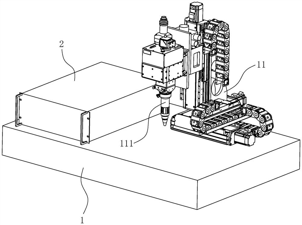
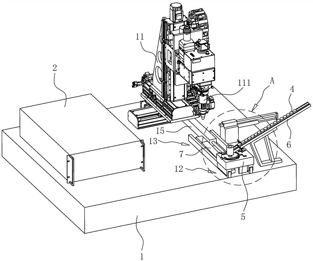
[0045] refer to image 3 A welding device for a cylindrical battery positive pole includes a base 1 and a laser generator 2 . The base 1 is provided with a bracket 11, and the bracket 11 is provided with a laser welding head 111, and the laser welding head 111 is connected with the bracket 11 through a screw nut structure, so that the laser welding head 111 can be adjusted up and down. The bracket 11 is connected to the base 1 through two sets of orthogonally arranged screw nut structures, so as to facilitate the movement of the bracket 11 in the horizontal plane. In this embodiment, the laser generator 2 is a fiber laser to improve the operation stability of the welding device.

[0046] refer to image 3 and Figure 4 , the base 1 is provided with a loading station 12 and a welding station 13; the welding station 13 is located below the laser welding head 111. The upper surface of the base 1 is fixed with a slide rail 14 by screws, one end of the slide rail 14 is located ...

Embodiment 2

[0059] The difference between this embodiment and embodiment 1 is:

[0060] refer to Figure 7 and Figure 8 , the base 1 is rotatably connected with a rotating disk 16 through a bearing, and the axial direction of the rotating shaft of the rotating disk 16 is arranged along the up-down direction. The number of mounting bases 5 may be one, and the number of mounting bases 5 may be two or even more; in this embodiment, the number of mounting bases 5 is six. All the mounting seats 5 are uniformly and distributed sequentially along the circumferential direction of the rotating disk 16 , and all the mounting seats 5 are welded and fixed to the rotating disk 16 . In this embodiment, the position for the operator to install the collector plate 3 is the clamping station 17 , and the position for the base 1 to weld the pusher seat 9 is the pusher station 18 . The feeding station 12, the clamping station 17, the welding station 13, and the pushing station 18 are arranged at interval...


PUM


Abstract

The invention discloses a welding device for a cylindrical battery positive pole column, and relates to the technical field of cylindrical battery accessory machining, the welding device comprises a base and a laser generator, the base is provided with a support, the support is provided with a laser welding head, and the laser welding head is connected with the laser generator; the base is provided with a mounting seat, and the upper surface of the mounting seat is downwards provided with a mounting hole for placing a positive pole; the inner side wall of the mounting hole is slidably provided with a feeding column for bearing the positive electrode column; the feeding column is connected with a driving piece used for driving the feeding column to slide. The upper surface of the mounting base is provided with a positioning arc plate used for abutting against the peripheral wall of the collector plate. The mounting seat is fixedly provided with an elastic pressing sheet for pressing the collector plate; when the peripheral wall of the collector plate abuts against the inner side wall of the positioning arc plate, the connecting hole of the collector plate is aligned with the mounting hole. The welding device has the advantages of being convenient and rapid to operate and beneficial to improving the welding efficiency between the positive pole and the collector plate.

Description

technical field [0001] The present application relates to the technical field of processing cylindrical battery accessories, in particular to a welding device for a positive pole of a cylindrical battery. Background technique [0002] Cylindrical battery is a battery with high capacity and long life, which includes different systems such as lithium iron phosphate, lithium cobalt oxide, lithium manganese oxide, cobalt-manganese mixture, and ternary materials. Cylindrical batteries generally include a cylindrical shell, one end of which is provided with a positive electrode current collector, and the other end is provided with a negative electrode current collector; the positive electrode current collector is welded and fixed with a positive pole, so that the cylindrical batteries can be connected in series from the end to the end. [0003] A welding device, with reference to figure 1 , which includes a base 1 and a laser generator 2; the base 1 is provided with a bracket 11,...

Claims


Application Information

Patent Timeline
Patent Type & Authority Applications(China)
IPC IPC(8): B23K26/21B23K26/08B23K26/70H01M50/566
CPCB23K26/21B23K26/0884B23K26/702H01M50/566Y02E60/10
Inventor 杨亚涛乐庸辉苏孙锦廖荣胜欧思意罗文鹏
Owner 柳州智德智能科技有限公司
Features
  • R&D
  • Intellectual Property
  • Life Sciences
  • Materials
  • Tech Scout
  • Unparalleled Data Quality
  • Higher Quality Content
  • 60% Fewer Hallucinations
Learn More