Unlock instant, AI-driven research and patent intelligence for your innovation.

Mechanical arm tool locking mechanism

A technology of locking mechanism and mechanical arm, which is applied in the direction of metal processing machine parts, manufacturing tools, positioning devices, etc., can solve the problem that the tool changing speed of the clamping mechanism is not fast enough, and achieves simple structure, improved working speed, and easy The effect of the operation

Pending Publication Date: 2022-05-17
ZHUHAI GREE INTELLIGENT EQUIP TECH RES INST CO LTD +2
View PDF6 Cites 0 Cited by
  • Summary
  • Abstract
  • Description
  • Claims
  • Application Information

AI Technical Summary

Problems solved by technology

Although the existing ATC double-arm tool changer can achieve tool clamping, the tool change speed of the tool change clamping mechanism is not fast enough

Method used


Image

  • Mechanical arm tool locking mechanism
  • Mechanical arm tool locking mechanism
  • Mechanical arm tool locking mechanism

Examples


Embodiment

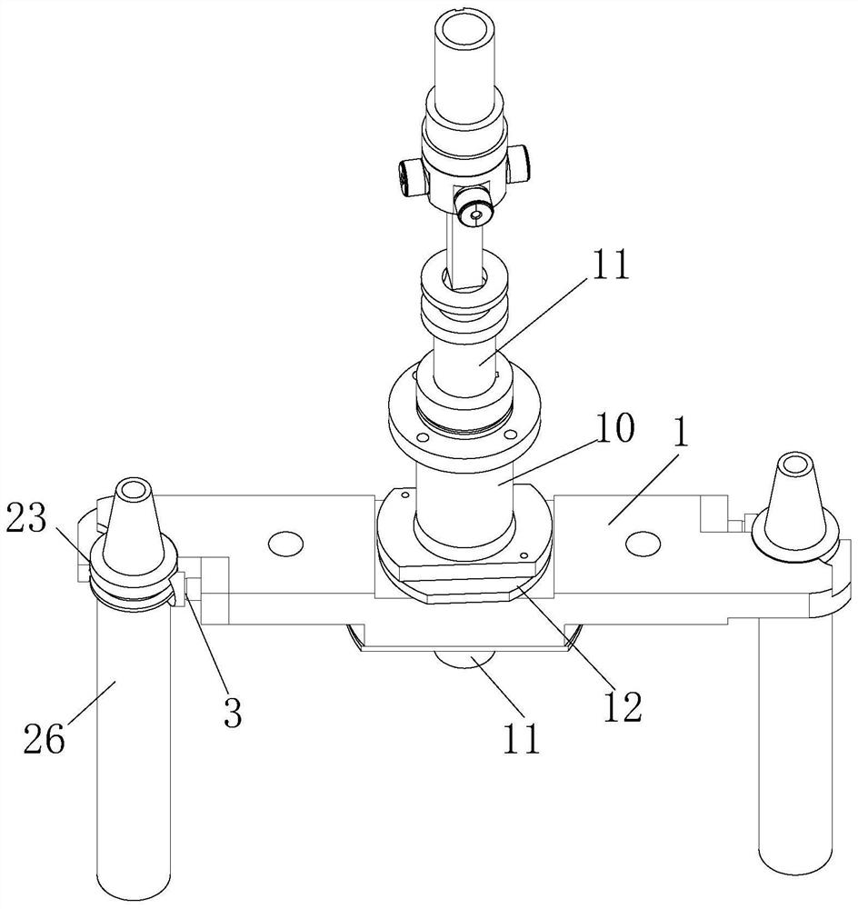
[0032] A mechanical arm tool locking mechanism disclosed in this embodiment, Figure 1-Figure 3 As shown, it includes a knife arm 1, the end of the knife arm 1 is provided with a jaw 2 and a handle locking rod 3, and the handle locking rod 3 extends along the length direction of the knife arm 1, the The first end 4 of the knife handle locking lever 3 points to the jaw 2, the tail end 5 of the knife handle locking lever 3 is inserted on the knife arm 1 and points to the middle part of the knife arm 1, and the knife The middle part of the arm 1 is provided with a limit block 6; when locking the knife handle locking lever 3, the limit block 6 rises in a direction perpendicular to the knife arm 1 and its side is locked against the knife handle The tail end 5 of the rod 3; when the handle locking rod 3 is unlocked, the stop block 6 descends in a direction perpendicular to the knife arm 1 and gives way for the handle locking rod 3 to move. Spatial location.

[0033] By setting the...


PUM


Abstract

The invention relates to the technical field of numerical control machine tools, in particular to a mechanical arm tool locking mechanism which comprises a tool arm, a clamping opening and a tool handle locking rod are arranged at the end of the tool arm, the tool handle locking rod extends in the length direction of the tool arm, the head end of the tool handle locking rod points to the clamping opening, and the tail end of the tool handle locking rod is inserted into the tool arm in a penetrating mode and points to the middle of the tool arm. A limiting block is arranged in the middle of the tool arm; when the cutter handle locking rod is locked, the limiting block ascends in the direction perpendicular to the cutter arm, and the side face of the limiting block abuts against the tail end of the cutter handle locking rod. When the cutter handle locking rod is unlocked, the limiting block descends in the direction perpendicular to the cutter arm, the space position where the cutter handle locking rod moves is reserved, and the mechanical arm cutter locking mechanism has the advantages that the cutter can be conveniently and rapidly locked and unlocked, and the mechanical arm cutter locking mechanism is good in locking effect and easy to operate.

Description

technical field [0001] The invention relates to the technical field of numerical control machine tools, in particular to a tool locking mechanism of a mechanical arm. Background technique [0002] The development of modern CNC machine tools is rapid. With the continuous development of industry, the parts processed by machine tools are becoming more and more complex, and the processing capacity required by machine tools is constantly increasing. In order to meet the different processing techniques of the same part and the processing requirements of different parts, it is necessary to change the spindle tool frequently. Fast automatic tool change can greatly reduce working hours and improve production efficiency. Although the existing ATC double-arm tool changer can realize tool clamping, the tool change speed of the tool changer clamping mechanism is not fast enough. Contents of the invention [0003] The purpose of the present invention is to avoid the deficiencies in th...

Claims


Application Information

Patent Timeline
IPC IPC(8): B23Q3/15
CPCB23Q3/1554
Inventor 曾琨黄树有刘代伟莫玉麟杨博会白晋
Owner ZHUHAI GREE INTELLIGENT EQUIP TECH RES INST CO LTD
Features
  • R&D
  • Intellectual Property
  • Life Sciences
  • Materials
  • Tech Scout
  • Unparalleled Data Quality
  • Higher Quality Content
  • 60% Fewer Hallucinations
Learn More