Back-wall double-slurry grouting simulation device and manufacturing and mounting method thereof

A technology for a simulation device and an installation method, which is applied to shaft equipment, earth-moving drilling, wellbore lining, etc., can solve problems such as the inability of the dual-liquid slurry to be reflected in time, the inability to mix the dual-liquid slurry evenly, and the short initial setting time of the dual-liquid slurry. , to achieve the effect of simple installation, less space occupation, and easy operation

Pending Publication Date: 2022-05-17
CHINA RAILWAY 14TH BUREAU GRP LARGE SHIELD ENG CO LTD +2
View PDF0 Cites 0 Cited by
  • Summary
  • Abstract
  • Description
  • Claims
  • Application Information

AI Technical Summary

Problems solved by technology

[0003] In summary, double-fluid grouting can solve the problem of segment floating to ensure the construction quality of the shield tunnel, but the initial setting time of the double-fluid grout is short. If the A , If B liquid is fully mixed first and then injected into the grouting pipe, the grout is likely to solidify during the pipeline transportation process, and the grout will block the grouting pipe.
However, if two pipes are used in parallel as in the actual double-liquid slurry construction process, so that the A and B liquids enter the shield tail gap and the formation and then mix themselves, the double-liquid slurry cannot be mixed evenly, and the effect of the double-liquid slurry cannot be reflected in time.

Method used


Image

  • Back-wall double-slurry grouting simulation device and manufacturing and mounting method thereof
  • Back-wall double-slurry grouting simulation device and manufacturing and mounting method thereof
  • Back-wall double-slurry grouting simulation device and manufacturing and mounting method thereof

Examples


Embodiment Construction

[0029] In order to make the purpose, features and advantages of the present invention more obvious and understandable, the technical solutions in the present invention will be clearly and completely described below in conjunction with the accompanying drawings in this specific embodiment. Obviously, the implementation described below Examples are only some embodiments of the present invention, but not all embodiments. Based on the embodiments in this patent, all other embodiments obtained by persons of ordinary skill in the art without creative efforts fall within the protection scope of this patent.

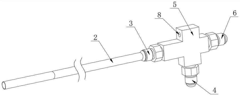
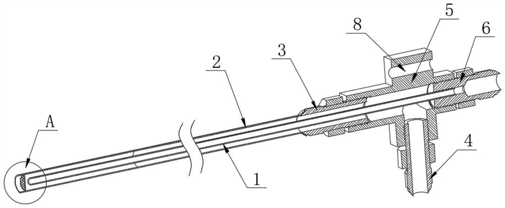
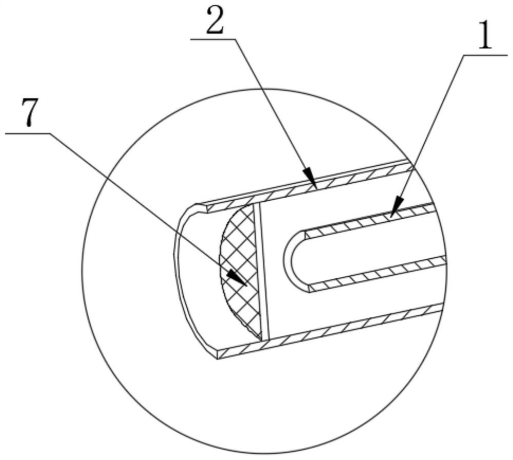
[0030] Such as Figure 1 to Figure 3 As shown, the present invention discloses a double-fluid grouting simulation device behind the wall, which includes multiple joints 5 of inner and outer tubes and inner tube 1 and outer tube 2 installed on the multiple joints 5 of inner and outer tubes. There are three interfaces on the multiple joints 5 of the layer pipe, the inner pipe joi...


PUM


Abstract

The invention belongs to the technical field of shield tunnel detection, and particularly relates to a back-wall double-slurry grouting simulation device and a manufacturing and installing method thereof.The back-wall double-slurry grouting simulation device comprises an inner-layer pipe multi-item connector, an outer-layer pipe, an inner-layer pipe and an outer-layer pipe, and the inner-layer pipe and the outer-layer pipe are installed on the inner-layer pipe multi-item connector and the outer-layer pipe multi-item connector; an inner-layer pipe joint is arranged in the right-side interface, one end of the inner-layer pipe is arranged in the inner-layer pipe joint, an outer-layer pipe joint is arranged in the left-side interface, one end of the outer-layer pipe is connected with the outer-layer pipe joint, the outer-layer pipe is arranged outside the inner-layer pipe, and a lower joint is arranged in the interface on the lower side of the multi-joint of the inner-layer pipe and the outer-layer pipe. The shield tunnel double-slurry synchronous grouting simulation device is used for simulating shield tunnel double-slurry synchronous grouting, cement slurry is introduced into the outer-layer pipe, a water glass solution is introduced into the inner-layer pipe, and the two kinds of slurry are introduced synchronously, so that the state and effect of shield tunnel double-slurry synchronous grouting can be simulated truly.

Description

technical field [0001] The invention belongs to the technical field of shield tunnel detection, and in particular relates to a double-fluid grouting simulation device behind a wall and methods for making and installing the same. Background technique [0002] In order to alleviate the pressure of ground traffic, many cities choose elevated roads or subways as traffic diversion methods. Among them, the construction of urban subway construction projects generally adopts the shield method. During the tunneling construction of the shield machine, since the outer diameter of the shield shell is larger than the outer diameter of the lining segment, when the segment comes out of the shield tail, the gap between the outer wall of the segment and the soil needs to be injected with grout to maintain the segment structure and stability of the surrounding soil. The traditional synchronous grouting slurry adopts a single-liquid award. Before the initial setting of the single-liquid slur...

Claims


Application Information

Patent Timeline
Patent Type & Authority Applications(China)
IPC IPC(8): E21D11/10E21D11/40
CPCE21D11/105E21D11/40
Inventor 孙旭涛陈鹏涂果彭小雨舒计城孙长松王建华陆野林志宇王士民何川
Owner CHINA RAILWAY 14TH BUREAU GRP LARGE SHIELD ENG CO LTD
Why Eureka
Try Eureka