
Microfluidic detection device

A detection device and microfluidic technology, applied in the field of microfluidics, can solve the problems of chip position offset, chip stuck, easily damaged detection device, etc., and achieve the effect of avoiding chip being stuck and accurately returning the card

Active Publication Date: 2022-05-17
TIANJIN DEXIANG BIOTECHNOLOGY CO LTD
View PDF21 Cites 0 Cited by
  • Summary
  • Abstract
  • Description
  • Claims
  • Application Information

AI Technical Summary

Problems solved by technology

However, during the pushing process of the device, the position of the chip often shifts, which causes the chip to be stuck, which makes the detection impossible and easily damages the detection device.

Method used


Image

  • Microfluidic detection device
  • Microfluidic detection device
  • Microfluidic detection device

Examples


Embodiment Construction

[0075] In order to make the purpose, technical solutions and advantages of the embodiments of the present invention more clear, the technical solutions in the embodiments of the present invention will be clearly and completely described below in conjunction with the drawings in the embodiments of the present invention. Apparently, the described embodiments are some, but not all, embodiments of the present invention. Based on the embodiments of the present invention, all other embodiments obtained by persons of ordinary skill in the art without making creative efforts belong to the protection scope of the present invention.

[0076] Herein, the use of suffixes such as 'module', 'part' or 'unit' for denoting elements is only to facilitate description of the present invention and has no specific meaning by itself. Therefore, 'module', 'part' or 'unit' may be used in combination.

[0077] Herein, the orientation or positional relationship indicated by the terms "upper", "lower", ...


PUM


Abstract

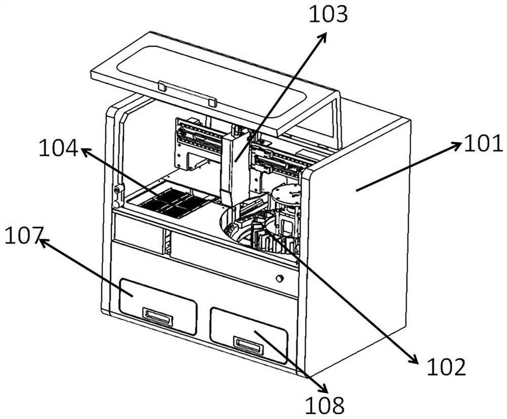
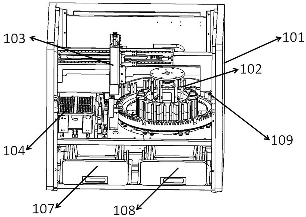
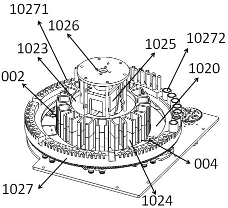
The invention provides a microfluidic detection device which comprises a rack, a centrifugal module, an automatic card loading module, an automatic card unloading module, a card loading station, a card unloading station, a waiting station corresponding to the card loading station, and a guide channel arranged between the waiting station and the card loading station, the automatic card feeding module comprises a card pushing piece and a first driving mechanism, the output end of the first driving mechanism is connected with the card pushing piece, and the card pushing piece is in surface contact with the micro-fluidic chip in the card pushing process, so that the stressed area is large, and the card can be stably and accurately pushed; the pushing force is large, so that in the process of stably pushing the micro-fluidic chip, the reaction cavity can be pushed to be close to the puncture structure, and automatic puncture is realized.

Description

technical field [0001] The invention relates to the field of microfluidic technology, in particular to a microfluidic detection device. Background technique [0002] Microfluidics refers to the science and technology involved in the use of micropipes (tens to hundreds of microns in size) to process or manipulate tiny fluids (nanoliters to attoliters in volume) and is a discipline involving chemistry, fluid physics , microelectronics, new materials, emerging interdisciplinary disciplines of biology and biomedical engineering. Because of the characteristics of miniaturization and integration, microfluidic devices are often called microfluidic chips. [0003] Centrifugal microfluidic technology integrates each reaction unit on a rotatable microfluidic chip through a structure such as a micropipe, and drives the liquid with centrifugal force, thereby completing the complex operation and reaction process of the liquid on the microfluidic chip, realizing various A technique for ...

Claims


Application Information

Patent Timeline
Patent Type & Authority Applications(China)
IPC IPC(8): G01N35/00G01N35/10B01L3/00
CPCG01N35/00029G01N35/00732G01N35/10B01L3/5027G01N2035/00039G01N2035/00158
Inventor 王伟权黄志刚王秀柱郝进学王丽岳晓宇
Owner TIANJIN DEXIANG BIOTECHNOLOGY CO LTD
Learn More