Dynamic grating pattern generation method and system for 3D measurement

A dynamic grating and pattern technology, which is applied in the field of optics and electronics, can solve the problems of low dynamic contrast, low optical utilization rate, complex system, etc.

Active Publication Date: 2022-05-17
杭州灵西机器人智能科技有限公司
View PDF3 Cites 0 Cited by
  • Summary
  • Abstract
  • Description
  • Claims
  • Application Information

AI Technical Summary

Problems solved by technology

[0004] 1. The system is complex and costly;
[0005] 2. Low optical utilization;
[0006] 3. In the case of limited volume, the brightness is low. At the same time, because the projector only blocks the light in the low gray area, or reflects it to another, but the light source at the corresponding position is always on, so the dynamic contrast is not high.
[0007] In the prior art, there is no better dynamic pattern generation scheme that can replace multi-purpose projectors that can produce higher contrast, measurement accuracy and resolution

Method used


Image

  • Dynamic grating pattern generation method and system for 3D measurement
  • Dynamic grating pattern generation method and system for 3D measurement
  • Dynamic grating pattern generation method and system for 3D measurement

Examples


Embodiment 1

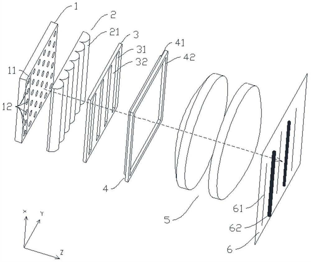
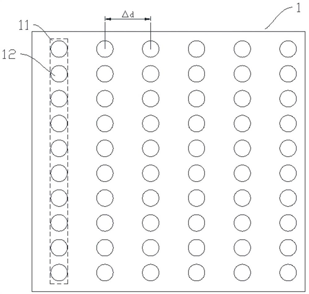
[0059] as attached figure 1 to attach Figure 6 As shown, the embodiment of the present invention provides a dynamic grating pattern generation system for 3D measurement, including a light-emitting unit array 1 for emitting high-frequency stroboscopic light, and the light-emitting unit array 1 includes several light-emitting units arranged in parallel and spaced apart 11. Each light-emitting unit 11 can be independently controlled, and the number of light-emitting units 11 can be 50, 100, etc. The specific number is set according to the required resolution.

[0060] Define the plane where the light-emitting unit array 1 is located as the reference plane, have the X-axis direction and the Y-axis direction perpendicular to each other, and define the light propagation path as the Z-axis direction;

[0061] A lens array, arranged on the light propagation path, for focusing the light in the Y-axis direction, the lens array includes a number of lens units, and each lens unit corres...

Embodiment 2

[0085] The difference between this embodiment and Embodiment 1 is that, as attached Figure 7 As shown, a first optical element 7 is added in the light propagation path, the first optical element 7 is located between the lens array and the grating shaping array 3, and is used to collimate the light in the X-axis direction, the first optical element 7 can be Single cylindrical lens, or cylindrical lens group, or DOE (diffractive optical element).

[0086] In this embodiment, the light emitting units 11 in the light emitting unit array 1 are one or more point light sources or line light sources along the X-axis direction.

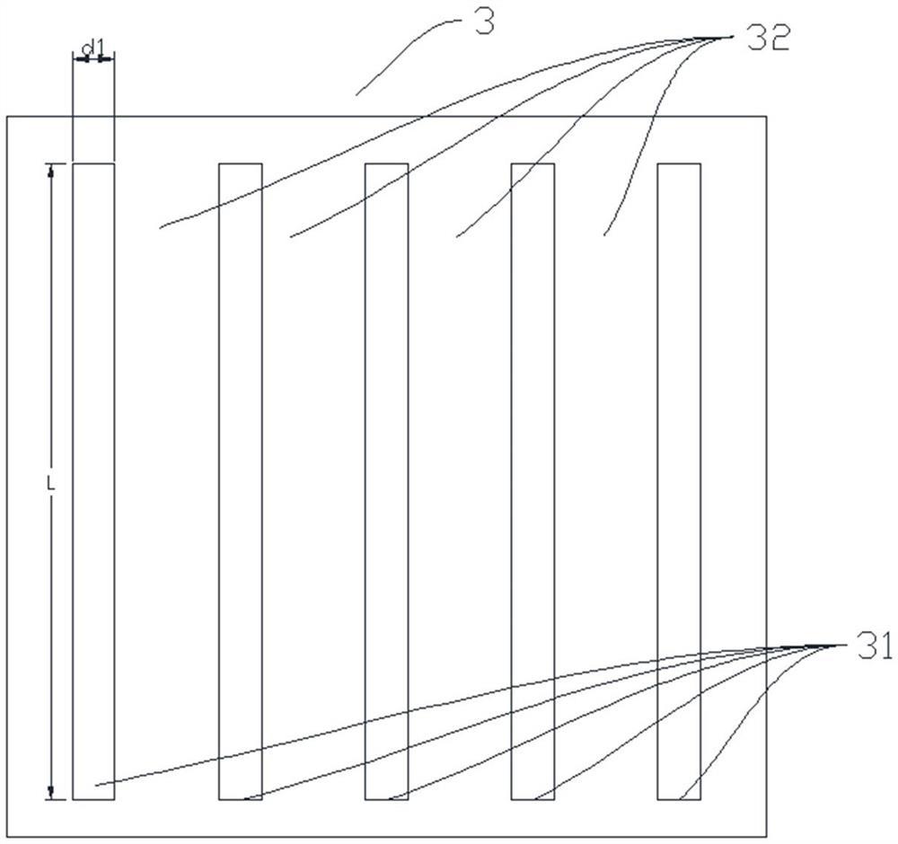
[0087] In order to ensure that the projected pattern on the working surface is in the shape of a grating strip, the length of the collimated light beam should be greater than the length L of the light-passing area 31 in the grating shaping array 3 . When the light emitting unit is a point light source, the focal length f of the first optical element 7 satisf...

Embodiment 3

[0091] The difference between this embodiment and Embodiment 1 is that, as attached Figure 8 As shown, a second optical element 8 is added in the propagation path of light, the second optical element 8 is located between the lens array and the grating shaping array 3, and is used to change the divergence angle of light in the X-axis direction, thereby controlling the working surface 6 The length of the projected pattern on the X-axis direction. The second optical element 8 can be a single cylindrical lens, or a cylindrical lens group, or a DOE (diffractive optical element).

[0092] Due to the addition of the second optical element to constrain the divergence angle of the light in the X-axis direction, the projection lens 5 of this embodiment can be composed of a cylindrical mirror, which only focuses the light beam passing through the grating shaping array 3 in the Y-axis direction, so that The generated grating strips are focused on the working surface 6 without changing t...


PUM


Abstract

The invention relates to a dynamic grating pattern generation method and system for 3D (three-dimensional) measurement, light emitted by a light-emitting unit array is converged to a grating shaping array by a lens array, after the light passes through the grating shaping array, a light beam in a Y-axis direction is generated through a light beam deflection mechanism for translation, and then the light beam is projected to a working surface through a projection lens. Projected structured light patterns generate element patterns through the grating shaping array, a plurality of light-emitting units which are arranged in parallel at intervals in the light-emitting unit array are used for independently controlling on-off changes and the frequency of stroboflash, and the light beam deflection mechanism rotates to generate grating stripe patterns with the brightness changing in the Y-axis direction under the combined action. Specifically, the light-emitting unit array determines the brightness of a grating strip in a projection pattern through the light source stroboscopic frequency, the precision of the element pattern is controlled through the grating shaping array, and the resolution of the projection pattern is controlled through the light beam deflection mechanism and the stroboscopic of the light-emitting unit, so that a dynamic grating pattern is formed on the working surface.

Description

technical field [0001] The invention relates to the technical fields of optics and electronics, in particular to a method and system for generating a dynamic grating pattern for 3D measurement. Background technique [0002] 3D measurement is being more and more widely used in various fields because it can obtain the depth information of objects. 3D measurement can be divided into line scanning method and surface scanning method according to the technical principle. The surface scanning method is fast and efficient, and has more application prospects. The 3D measurement of the surface scanning method generally needs to project structured light to the object, and use the camera to capture the pattern to calculate the three-dimensional point cloud data. The projected structured light is a specific pattern, such as a speckle pattern. [0003] If the projected structured light is a speckle pattern, only one picture is enough, but the measurement accuracy is not high. For scene...

Claims


Application Information

Patent Timeline
Patent Type & Authority Applications(China)
IPC IPC(8): G02B27/09G02B27/00G02B26/08
CPCG02B27/0944G02B27/00G02B26/0875
Inventor 王灿丁丁
Owner 杭州灵西机器人智能科技有限公司
Why Eureka
Try Eureka