
Tunnel back break numerical calculation method based on laser point cloud measurement

A technology of laser point cloud and numerical calculation, applied in calculation, image data processing, instruments, etc., can solve the problems of inability to batch calculation and poor universality, and achieve the effect of reasonable and feasible calculation method, reasonable establishment and wide application range

Pending Publication Date: 2022-05-17
CHINA RAILWAY FIRST SURVEY & DESIGN INST GRP
View PDF1 Cites 0 Cited by
  • Summary
  • Abstract
  • Description
  • Claims
  • Application Information

AI Technical Summary

Problems solved by technology

Different tunnels have different designed outer contours, which can only be calculated for specific types of tunnels, and the universality is poor
[0004] Liang Chao and others published the article "A Method for Quickly Obtaining Measurement Data of Overburden and Underbreak of Tunnel Initial Support". This article calculates the tunnel section composed of multiple arcs, and uses the geometric method through simple programming of the Casio calculator combined with the three-dimensional coordinates of the total station Back-calculate the over-under-mining value of the point to be tested. Only one detection point’s over- and under-mining value can be detected at a time, and it cannot be calculated in batches
[0005] Patent [CN108871268A] "A Numerical Calculation Method for Over- and Under-excavation of Tunnels Based on Laser Point Cloud", which provides a numerical calculation method for over- and under-excavation of tunnels based on laser point clouds. Underbreak data, this method is only applicable to numerical calculation of overbreak and underbreak for tunnels composed of arc segments

Method used


Image

  • Tunnel back break numerical calculation method based on laser point cloud measurement
  • Tunnel back break numerical calculation method based on laser point cloud measurement
  • Tunnel back break numerical calculation method based on laser point cloud measurement

Examples


Embodiment Construction

[0026] The present invention will be described in detail below in combination with specific embodiments.

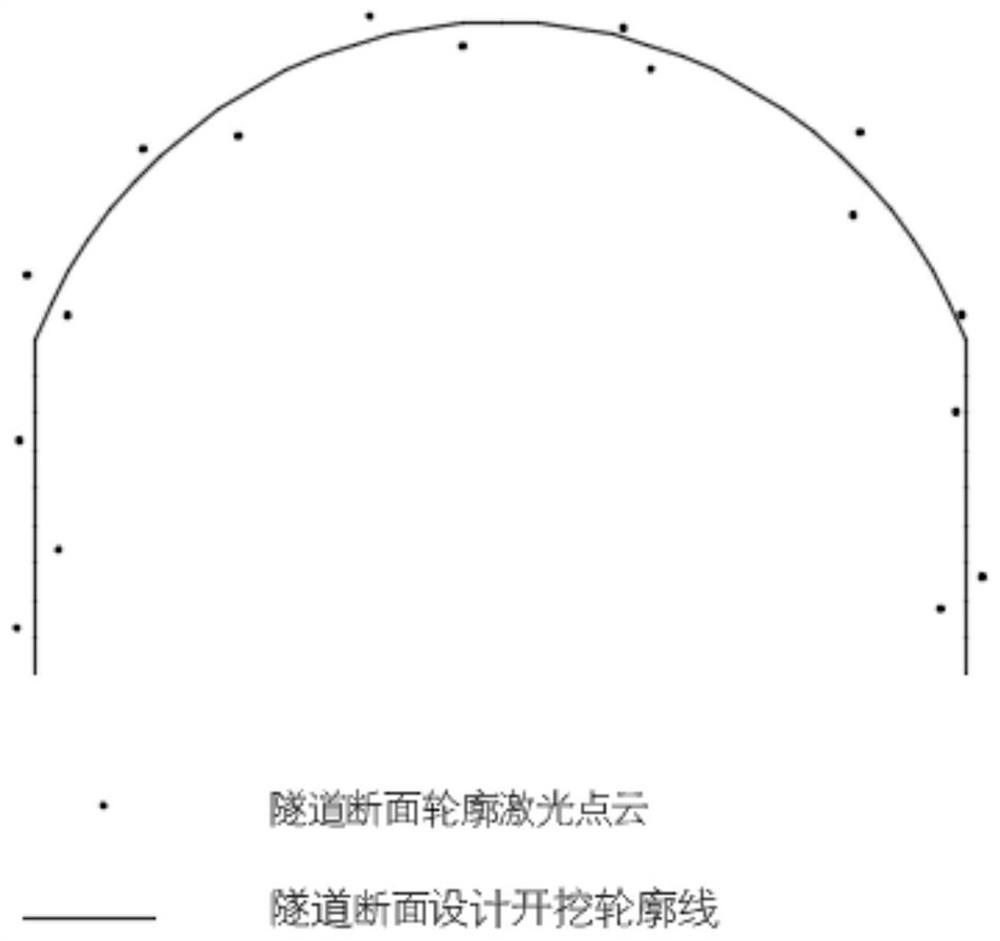
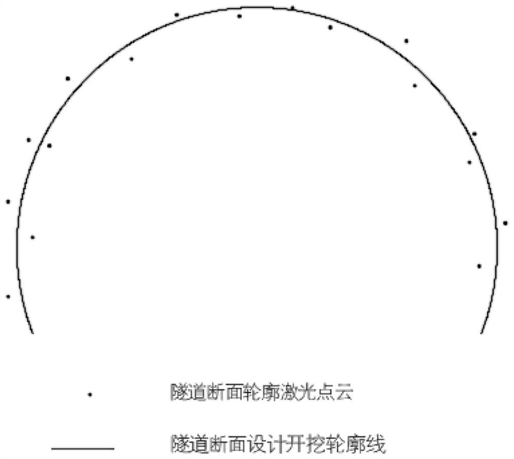
[0027] figure 2 Design excavation contours and point clouds for doorway type tunnels

[0028] This embodiment takes the door-type tunnel as an example to describe the present invention in detail, specifically including the following steps:

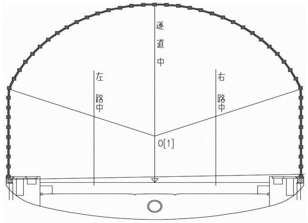
[0029] Step 1: Obtain the design drawing of the section profile of the portal-type tunnel, and establish the XOY plane coordinate system; the XOY plane coordinate system is specifically: the center line of the tunnel at the design elevation is the coordinate origin, the X axis is the horizontal line of the origin, and the Y axis is the horizontal line with the tunnel straight lines with coincident centerlines;

[0030] Step 2: Connect the tunnel section excavation profile of the design drawing into a curve C; the tunnel section of the design drawing is generally composed of multiple arcs or arcs and straight lines. The arcs and str...


PUM


Abstract

The invention discloses a tunnel back break numerical calculation method based on laser point cloud measurement. An existing measurement method for carrying out tunnel back break by utilizing laser point cloud is poor in universality when being used for carrying out calculation on tunnels of specific types. According to the method, an XOY coordinate system is established, tunnel section excavation contours on a tunnel section contour design drawing are connected into a curve C, the curve C is equally divided, and equally-divided points are connected into a line S in the clockwise direction; converting the tunnel section contour laser point cloud data into an XOY coordinate system; and searching a line segment closest to the jth laser point cloud on the S, and calculating the distance from the jth laser point cloud to the closest line segment, namely the back break numerical value of the jth laser point cloud. The method can be used for extracting the over-excavation and under-excavation values of various types of tunnels, can be used for quickly acquiring the over-excavation and under-excavation values, and provides a guarantee for the tunnel construction quality.

Description

technical field [0001] The invention belongs to the technical field of laser point cloud measurement, and in particular relates to a numerical calculation method for over- and under-excavation of tunnels based on laser point cloud measurement. Background technique [0002] In the process of tunnel construction, under the influence of geological conditions, surrounding rock structure, rock structure, hydrology and gas and other factors, tunnel over-excavation and under-excavation are often encountered. The formation process of over- and under-excavation is that excavation will cause rock blocks to collapse, which will cause surrounding rock disturbances and lead to changes in the stress state of surrounding rocks. When the shear strength of the structural plane of the rock mass is lower than the sliding force, part of the rock mass will slide, resulting in over-excavation. under-excavation phenomenon. Excessive over-excavation leads to the increase of primary shotcrete. In t...

Claims


Application Information

Patent Timeline
IPC IPC(8): G06T17/20G06T17/10
CPCG06T17/20G06T17/10
Inventor 杨秉岐张邵华王建红武瑞宏田社权袁永信张占忠张卫龙杨远超肖永飞田生辉石硕
Owner CHINA RAILWAY FIRST SURVEY & DESIGN INST GRP
Features
  • Generate Ideas
  • Intellectual Property
  • Life Sciences
  • Materials
  • Tech Scout
  • Unparalleled Data Quality
  • Higher Quality Content
  • 60% Fewer Hallucinations
Learn More