Bragg reflector and light emitting diode with Bragg reflector

A technology of Bragg mirrors and light-emitting diodes, applied in semiconductor devices, electrical components, circuits, etc., can solve the problems of low machine utilization rate and inability to reflect various light types

Pending Publication Date: 2022-05-24
JIANGXI ZHAO CHI SEMICON CO LTD
View PDF0 Cites 4 Cited by
  • Summary
  • Abstract
  • Description
  • Claims
  • Application Information

AI Technical Summary

Problems solved by technology

[0004] Based on this, the object of the present invention is to provide a Bragg reflector and a light-emitting diode with a Bragg reflector, which solves the problem in the background art that the two-stage Bragg reflector cannot reflect various light types, resulting in low machine utilization rate.

Method used


Image

  • Bragg reflector and light emitting diode with Bragg reflector
  • Bragg reflector and light emitting diode with Bragg reflector
  • Bragg reflector and light emitting diode with Bragg reflector

Examples


Embodiment 1

[0041] The principle of Bragg mirror reflection is that Fresnel reflection occurs at each interface of the two materials of the Bragg mirror. At the working wavelength, the optical path difference of the reflected light at two adjacent interfaces is half the wavelength, and the sign of the reflection coefficient at the interface also changes. Therefore, all reflected light at the interface interferes destructively, resulting in a strong reflection. The reflectivity is determined by the number of layers of the material and the difference in refractive index between the materials. The reflection bandwidth is mainly determined by the refractive index difference.

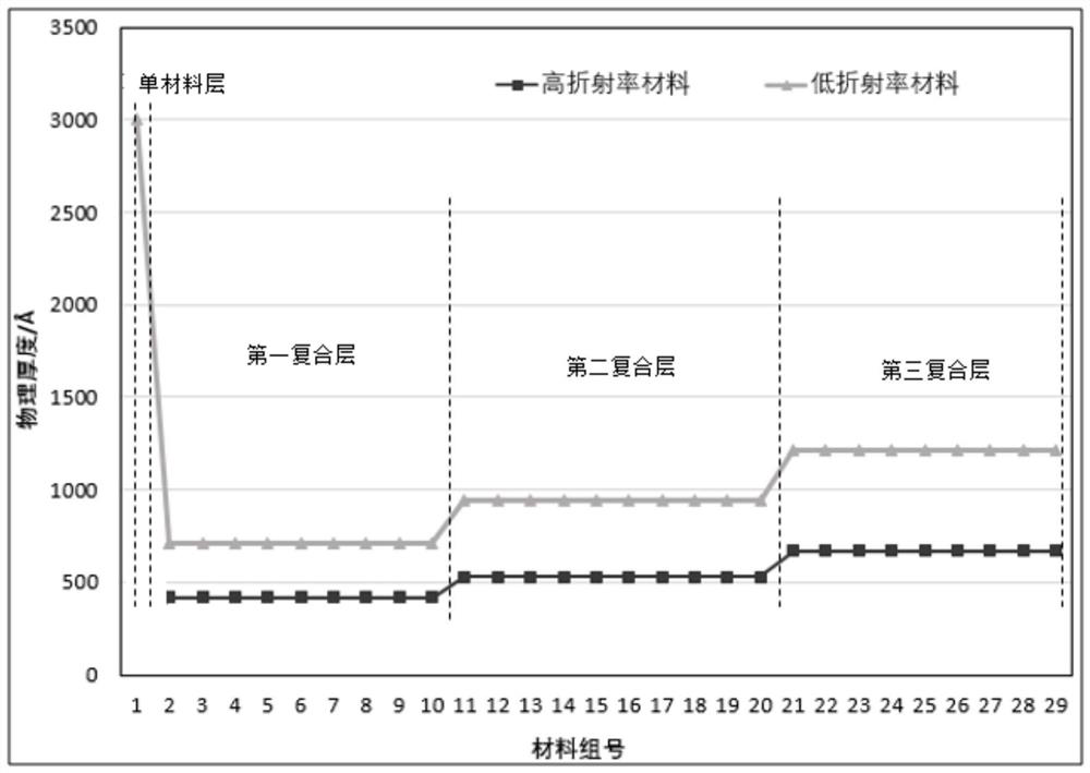
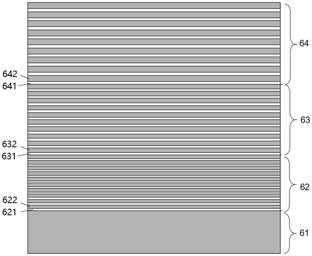
[0042] see figure 2 , shows a schematic cross-sectional view of the Bragg mirror in this embodiment, including a Bragg mirror single-material layer 61, a Bragg mirror first composite layer 62, a Bragg mirror second composite layer 63, and a Bragg mirror third composite layer 64 , wherein, the first composite layer 6...

Embodiment 2

[0055] See Figure 5 , which is a schematic cross-sectional view of the light-emitting diode in this embodiment, and the light-emitting diode in this embodiment includes the Bragg reflector in the above-mentioned first embodiment.

[0056] The light-emitting diode in this embodiment is a front-mounted diode, including a Bragg mirror third composite layer 64, a Bragg mirror second composite layer 63, a Bragg mirror first composite layer 62, a Bragg mirror single-material layer 61, a substrate 71. Epitaxial layer 72, current blocking layer 73, current spreading layer 74, PAD conductive layer 75; epitaxial layer 61 includes N-type semiconductor layer 721, active light-emitting layer 722, P-type semiconductor layer 723.

[0057] The Bragg reflector single-material layer 61 is located on the side of the substrate 71 away from the active light-emitting region 722 in the epitaxial layer 61, the Bragg reflector first composite layer 62 is located on the side of the Bragg reflector sin...

Embodiment 3

[0060] refer to Image 6 , is a schematic cross-sectional view of the light-emitting diode in this embodiment, and the light-emitting diode in this embodiment includes the Bragg reflector in the above-mentioned first embodiment.

[0061] The light-emitting diode in this embodiment is a flip-chip light-emitting diode, including a substrate 71, an epitaxial layer 72, a current blocking layer 73, a current spreading layer 74, a PAD conductive layer 75, a Bragg mirror single-material layer 61, a Bragg mirror first The composite layer 62 , the second composite layer of Bragg mirror 63 , the third composite layer of Bragg mirror 64 , and the pad layer 81 ; the epitaxial layer includes an N-type semiconductor layer 721 , an active light-emitting layer 722 , and a P-type semiconductor layer 723 .

[0062] The Bragg reflection layer single-material layer 61, the first composite layer 62, the second composite layer 63, and the third composite layer 64 are all interposed between the acti...


PUM

PropertyMeasurementUnit
reflectanceaaaaaaaaaa
refractive indexaaaaaaaaaa

Abstract

The invention provides a Bragg reflector and a light-emitting diode with the Bragg reflector. The Bragg reflector comprises a single material layer and a light-emitting layer, wherein the single material layer is made of a single-layer low-refractive-index material; the first composite layer comprises a plurality of groups of material groups with high refractive indexes and low refractive indexes which are alternately stacked; the second composite layer comprises a plurality of groups of material groups with high refractive indexes and low refractive indexes which are alternately stacked; the third composite layer comprises a plurality of groups of material groups with high refractive indexes and low refractive indexes which are alternately stacked; the thicknesses of each group of low-refractive-index materials of the first composite layer, the second composite layer and the third composite layer and the low-refractive-index materials of the single-material layer are gradually increased in sequence; and the thicknesses of each group of high-refractive-index materials of the first composite layer, the second composite layer and the third composite layer are gradually increased in sequence. According to the Bragg reflector and the light-emitting diode with the Bragg reflector, the Bragg reflector formed by superposing the four layers of materials with different thicknesses and high and low refractive indexes is arranged, so that the Bragg reflector can reflect various light sources, and the process stability and the machine activation are improved.

Description

technical field [0001] The present invention relates to the technical field of semiconductors, in particular to a Bragg reflector and a light emitting diode with the Bragg reflector. Background technique [0002] Light Emitting Diode (LED) is a solid-state light-emitting component made of semiconductor materials. It generally uses a combination of III-V chemical elements such as gallium phosphide, gallium arsenide or gallium nitride. The semiconductor applies a voltage, so that the holes and electrons meet in a large number in the light-emitting layer under the action of the electrode voltage to generate recombination. At this time, the electrons will drop to a lower energy level, and at the same time, they will be released in the mode of photons, so that the electrical energy can be converted into light to achieve light emission. Effect. [0003] The Bragg reflector applied to the light-emitting diode chip in the prior art includes two layers. The first layer and the secon...

Claims


Application Information

Patent Timeline
Patent Type & Authority Applications(China)
IPC IPC(8): H01L33/10H01L33/14
CPCH01L33/10H01L33/145
Inventor 李文涛鲁洋简弘安张星星胡加辉金从龙顾伟
Owner JIANGXI ZHAO CHI SEMICON CO LTD
Why Eureka
Try Eureka