Uniform cleaning device suitable for cleaning structure of precision machine tool equipment

A precision machine tool and cleaning device technology, applied in metal processing equipment, lighting and heating equipment, cleaning methods using liquids, etc., can solve the problems of low water pressure, low air pressure, insufficient decontamination ability, poor cleaning effect, etc., to achieve increased Great rinsing blow force, good rinsing effect and drying effect, and even cleaning effect

Active Publication Date: 2022-05-27
沈阳和研科技股份有限公司
View PDF8 Cites 0 Cited by
  • Summary
  • Abstract
  • Description
  • Claims
  • Application Information

AI Technical Summary

Problems solved by technology

[0003] The characteristics of the prior art are: most of the traditional structural cleaning modules with continuous rows of nozzles adopt the scheme of cross-arranging and distributing more water spray heads and air spray heads to achieve a long-distance cleaning effect; The fan-shaped structure is mostly used for the water head and the air spray head, and the spraying scheme of the fan-shaped nozzle has the advantage of large coverage, but the disadvantage is that the water pressure and air pressure on both sides of the fan shape are small, which brings insufficient decontamination ability and poor cleaning effect
However, if the problem of poor cleaning effect is to be solved, more water nozzles and air nozzles must be installed, which will cause waste of water and air; moreover, there will be more crossing of air and water paths, which will cause loss

Method used


Image

  • Uniform cleaning device suitable for cleaning structure of precision machine tool equipment
  • Uniform cleaning device suitable for cleaning structure of precision machine tool equipment
  • Uniform cleaning device suitable for cleaning structure of precision machine tool equipment

Examples


Embodiment Construction

[0027] In order to make the technical problems, technical solutions and beneficial effects solved by the present invention clearer, the present invention will be further described in detail below with reference to the accompanying drawings and specific embodiments. It should be understood that the specific embodiments described herein are only used to explain the present invention, but not to limit the present invention.

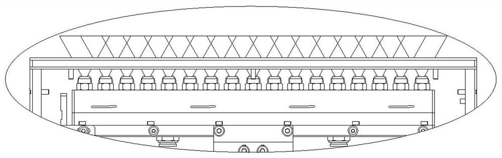
[0028] like figure 1 Shown is a schematic diagram of the upper part of the traditional continuous row nozzle structure cleaning module, which adopts a structural design in which more water spray heads and air jet heads are arranged and distributed in a cross manner to achieve a longer distance cleaning effect; this traditional continuous row nozzles The water spray head and air jet head of the structural cleaning module are fan-shaped structures, and the water sprayed is also fan-shaped. The advantage is that the coverage area is large. The cleaning effect ...


PUM


Abstract

The invention discloses a uniform cleaning device suitable for a cleaning structure of precision machine tool equipment, which comprises a box body, an air injection and water spraying assembly, guide structures and an anti-leakage structure are arranged in the box body, the guide structures are symmetrically mounted on opposite box walls in the box body, the air injection and water spraying assembly is connected with a power cylinder, and the power cylinder is arranged below the outside of the box body. The air and water spraying assembly can be driven by the power air cylinder to reciprocate in the box body along the guide structure, and an anti-leakage structure is arranged at the bottom of the box body below the air and water spraying assembly; a water vapor spraying opening is formed in the top of the box body above the air spraying and water spraying assembly, the air spraying and water spraying assembly comprises an air spraying knife, a water spraying knife, a knife holder and a supporting column, the air spraying knife and the water spraying knife are the same in structure and are connected to the knife holder in parallel, the supporting column is connected to the lower portion of the knife holder and penetrates through the anti-leakage structure, and the bottom of the box body is connected with the power air cylinder. A continuous water curtain and a continuous air curtain can be sprayed out, the integration degree is higher, and cleaning is more uniform.

Description

technical field [0001] The invention belongs to the technical field of precision machine tool equipment components, and in particular relates to a uniform cleaning device suitable for cleaning structures of precision machine tool equipment. Background technique [0002] After the precision CNC machining machine equipment used for cutting completes the cutting of semi-finished products, it will perform image recognition to distinguish the cutting quality, so as to classify the product quality level. Computer judgments that interfere with subsequent image recognition processes, resulting in quality classification errors. At present, the surface cleaning work of the small workpiece after cutting is carried out by the traditional cleaning module of continuous row nozzle structure, such as figure 1 Shown is the schematic diagram of the upper part of the traditional cleaning module with continuous nozzle structure; small workpieces are adsorbed and carried by the suction cups con...

Claims


Application Information

Patent Timeline
Patent Type & Authority Applications(China)
IPC IPC(8): B08B3/02F26B21/00B23Q11/00
CPCB08B3/022F26B21/004B23Q11/0042Y02P70/10
Inventor 张明明袁慧珠杨盛刘苏阳石文徐双双
Owner 沈阳和研科技股份有限公司
Why Eureka
Try Eureka