Efficient automatic hot stamping forming equipment

A technology of hot stamping and hot stamping, which is applied in the field of parts processing, can solve problems such as low degree of automation, unable to discharge mold air pressure, and defective parts, and achieve the effect of improving precision

Pending Publication Date: 2022-05-27
HEFEI METALFORMING MACHINE TOOL
View PDF9 Cites 0 Cited by
  • Summary
  • Abstract
  • Description
  • Claims
  • Application Information

AI Technical Summary

Problems solved by technology

[0002] Hot stamping is a part processing method. The current thermoforming method can be divided into direct thermoforming and indirect thermoforming according to the heating method. As an emerging processing method, indirect thermoforming has many advantages: no part size and shape restrictions, Parts of any shape and depth of drawing can be produced. All parts produced by ordinary cold stamping process and direct hot forming process can be produced by indirect hot forming process; there is no deformation process of the workpiece in the core quenching process, and the mold stress distribution is uniform. There is almost no relative movement between the workpiece and the mold surface, so that the mold loss is very small, and the surface of the workpiece is hardly damaged; the blanking process and laser cutting process are completed by the cold stamping line in the preforming process, which improves production efficiency and reduces the investment in production line construction , the welding process is canceled, and larger parts such as the middle channel, front wall, door sill, etc. can be processed as a whole and formed at one time; the indirect hot forming process first cold stamps the steel plate, then heats it, puts it into a water-cooled mold, and presses it in a high-speed special hydraulic press Quenching is realized under the hood, and martensitic ultra-high-strength hot-formed parts are pressed, and the hot parts are placed in a cold mold to harden and determine the final geometry. May create air pressure that cannot be vented, resulting in defective parts

Method used


Image

  • Efficient automatic hot stamping forming equipment
  • Efficient automatic hot stamping forming equipment
  • Efficient automatic hot stamping forming equipment

Examples


Embodiment 1

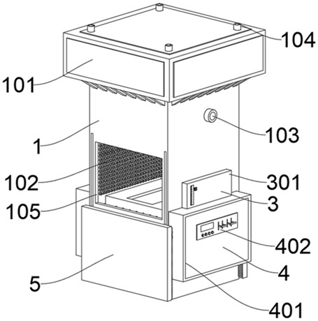
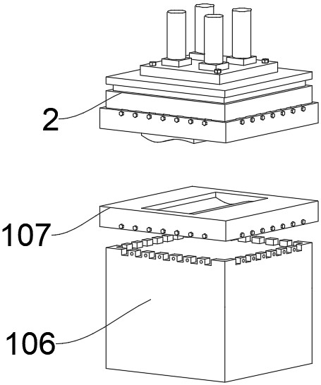
[0029] Please refer to Figures 1-3, an efficient automatic hot stamping forming equipment, including a hot stamping furnace 1, a stamping device 2 is connected to the inner side of the top of the hot stamping furnace 1, and a control device 3 is installed on both sides of the hot stamping furnace 1. Opening and closing devices 4 are installed on both sides of the stamping furnace 1 , and the opening and closing devices 4 are located below the control device 3 , and furnace doors 5 are installed at the front and rear ends of the hot stamping furnace 1 .

[0030] The hot stamping furnace 1 includes a furnace wall, the top of the furnace wall is welded with a furnace roof 101, the top of the furnace roof 101 is provided with an air outlet 104, and the interior of the furnace roof 101 is provided with an air outlet, and the air outlet is communicated with the air outlet 104. There are nozzles 102 on both sides, and a water inlet 103 is arranged on the outside of both sides of the f...

Embodiment 2

[0034] Referring to FIG. 4, the difference in combination with Embodiment 1 is that the control device 3 includes a casing 301, and a thermally conductive column 302 is inserted on the inner wall of the casing 301, and the inner end of the thermally conductive column 302 penetrates the furnace wall and the hot stamping furnace. 1 is in contact with the internal air, the outer end of the heat-conducting column 302 is sleeved with mercury balls 303, the top of the mercury balls 303 is connected with a hollow tube 304, the inside of the hollow tube 304 is movable with a metal contact 305, and the outer surface of the shell 301 is connected with a The adjustment pointer is fixedly connected with the metal contact 305, the rear end of the metal contact 305 is electrically connected with an electromagnet 306, the top inner wall of the housing 301 is fixedly connected with a hoisting spring 308, and the bottom of the hoisting spring 308 is fixedly connected with iron Block 307, and th...

Embodiment 3

[0037] Referring to Figures 5-6, the basic difference between Embodiments 1 and 2 is that the opening and closing device 4 includes a protective shell 401, the protective shell 401 is welded on both sides of the base 106, and the surface of the protective shell 401 is provided with a control 402, the bottom inner wall of the base 106 is screwed with a motor 403, the output end of the motor 403 is fixedly connected with a driving gear 404, and the driving gear 404 is located inside the protective shell 401, and the top of the driving gear 404 is meshed with a driven gear 405. A bevel gear A406 is meshed with the outside of the driven gear 405, a bevel gear B407 is coaxially connected to the front and rear of the bevel gear A406, and a control gear 408 is meshed with the two bevel gears B407.

[0038] The furnace door 5 includes a door panel 501, a surface of the door panel 501 is welded with a rack 502 at both ends, the rack 502 is engaged with the control gear 408, and a side o...


PUM


Abstract

The invention discloses efficient automatic hot stamping forming equipment, and belongs to the technical field of part machining. Efficient automatic hot stamping forming equipment comprises a hot stamping furnace, a stamping device is connected to the inner side of the top of the hot stamping furnace, control devices are installed on the two sides of the hot stamping furnace, opening and closing devices are installed on the two sides of the hot stamping furnace, and the opening and closing devices are located below the control devices. And furnace doors are mounted at the front and rear ends of the hot stamping furnace. The problems that traditional indirect thermal forming equipment is low in automation degree and poor in pressure relief capacity are solved.

Description

technical field [0001] The invention relates to the technical field of parts processing, and more particularly, to an efficient automatic hot stamping forming equipment. Background technique [0002] Hot stamping is a part processing method. The current hot forming method can be divided into direct thermoforming and indirect thermoforming according to the heating method. As an emerging processing method, indirect thermoforming has many advantages: there are no restrictions on the size and shape of parts, Parts of any shape and depth of drawing can be produced. All parts produced by ordinary cold stamping process and direct hot forming process can be produced by indirect hot forming process; in the core quenching process, the workpiece has no deformation process, and the mold stress distribution is uniform. There is almost no relative movement between the workpiece and the surface of the mold, so that the mold loss is very small, and the surface of the workpiece is hardly dam...

Claims


Application Information

Patent Timeline
IPC IPC(8): B21D22/02B21D37/16
CPCB21D22/02B21D37/16
Inventor 严建文李贵闪王磊张海杰胡彬彬印志峰方昆刘琼
Owner HEFEI METALFORMING MACHINE TOOL
Why Eureka
Try Eureka