Supercharge Your Innovation With Domain-Expert AI Agents!

Circulating tank for silicon wafer corrosion

A circulating tank and silicon wafer technology, applied in the final product manufacturing, post-processing details, polycrystalline material growth, etc., can solve the problems of easily affecting the corrosion effect of silicon wafers, easy waste of etching solution, etc., to meet the corrosion requirements and ensure corrosion. effect, the effect of reducing waste

Active Publication Date: 2022-05-27
江苏英思特半导体科技有限公司
View PDF4 Cites 0 Cited by
  • Summary
  • Abstract
  • Description
  • Claims
  • Application Information

AI Technical Summary

Problems solved by technology

It is also possible to use the preferred etching method on the surface of silicon atoms, that is, place the silicon wafer horizontally in the pickling tank, and the defective parts can be observed with the naked eye. In the prior art, the circulation mode of the etching solution inside the pickling tank is mostly four weeks Outward circulation, that is, no matter how many silicon wafers are stored in the flower basket, it must be full of liquid medicine. However, when this pickling tank is used for experimental equipment, there may only be a few silicon wafers inside the pickling tank, which means As a result, the corrosive liquid in the full tank is easy to waste, and if only a corresponding amount of corrosive liquid is added to the inside of the pickling tank according to the number of silicon wafers, since the corrosive liquid is volatile, and as the corrosive liquid corrodes the silicon wafers, the corrosive liquid will There will also be a certain amount of consumption by itself, which requires the experimenter to look at the side of the pickling tank at any time. Once negligent, it is easy to affect the corrosion effect of the silicon wafer

Method used


Image

  • Circulating tank for silicon wafer corrosion
  • Circulating tank for silicon wafer corrosion
  • Circulating tank for silicon wafer corrosion

Examples


Embodiment Construction

[0017] In order to deepen the understanding of the present invention, the present invention will be further described below in conjunction with the embodiments and accompanying drawings. The embodiments are only used to explain the present invention and do not constitute a limitation to the protection scope of the present invention.

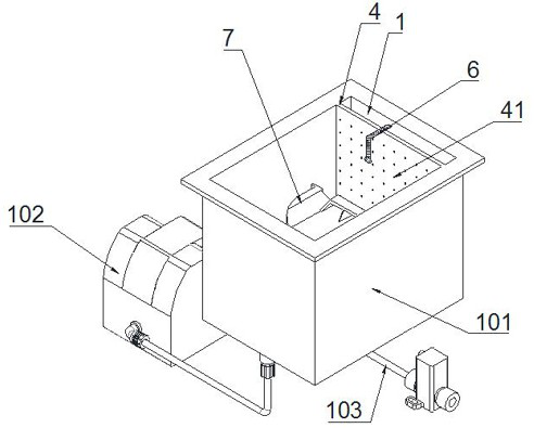
[0018] like Figure 1 to Figure 3 It is a specific embodiment of the present invention, and its structure includes a tank body 101. The left and right sides of the tank body 101 are respectively provided with a liquid addition tank 1 and a circulation flow tank 2. The width of the liquid addition tank 1 is equal to the width of the circulation flow tank 2 The immersion tank 3 is formed between the liquid feeding tank 1 and the circulation flow tank 2, and a liquid outlet plate 4 is provided at the junction of the liquid feeding tank 1 and the liquid immersion tank 3, and the liquid outlet plate 4 is evenly distributed from top to bottom. Leakage ...


PUM


Abstract

The circulating tank structurally comprises a tank body and is characterized in that a liquid adding tank and a circulating tank are arranged on the left side and the right side of the tank body respectively, the width of the liquid adding tank is equal to that of the circulating tank, a liquid immersion tank is formed between the liquid adding tank and the circulating tank, and a liquid outlet plate is arranged at the joint of the liquid adding tank and the liquid immersion tank; a plurality of liquid leakage holes are evenly distributed in the liquid outlet plate from top to bottom, a liquid level calibration plate is arranged at the joint of the circulation groove and the immersion groove, the liquid level calibration plate is lower than the liquid outlet plate, the liquid adding groove and the circulation groove are communicated with each other and provided with a circulation pump, and a liquid outlet pipeline is arranged at the bottom of the immersion groove. And a liquid level difference detection piece is arranged between the immersion liquid tank and the liquid adding tank and is used for judging the liquid level difference between the immersion liquid tank and the liquid adding tank, and the continuous immersion corrosion effect of the silicon wafer is ensured.

Description

Technical field: [0001] The invention relates to the technical field of production of silicon material processing equipment, in particular to a circulation tank for silicon wafer corrosion. Background technique: [0002] During the growth process of single crystal silicon, there will be some other impurities or the instability of atomic arrangement, which will cause errors in the crystal arrangement, resulting in the generation of point defects and line defects. For such point defects and line defects, it is necessary to observe with the aid of microscopes, electron microscopes and other instruments. It is also possible to use the preferred etching method on the surface of silicon atoms, that is, place the silicon wafer horizontally in the pickling tank, and the defective parts can be observed with the naked eye. In the prior art, the circulation mode of the etching solution inside the pickling tank is mostly four weeks Outward circulation, that is, no matter how many silic...

Claims


Application Information

Patent Timeline
IPC IPC(8): C30B33/10C30B29/06
CPCC30B29/06C30B33/10Y02P70/50
Inventor 管选伟孙国浩
Owner 江苏英思特半导体科技有限公司
Features
  • R&D
  • Intellectual Property
  • Life Sciences
  • Materials
  • Tech Scout
  • Unparalleled Data Quality
  • Higher Quality Content
  • 60% Fewer Hallucinations
Learn More