
Improved assembly structure on mini-tiller clutch

An improved structure and clutch technology, which is applied in the direction of mechanical drive clutches, clutches, friction clutches, etc., can solve the problems of short service life, difficult maintenance, and low connection accuracy of micro tillage machines, so as to prevent separation and improve the use of The effect that the precision of life and separation is high

Pending Publication Date: 2022-05-27
湘潭富民农业机械有限公司
View PDF0 Cites 0 Cited by
  • Summary
  • Abstract
  • Description
  • Claims
  • Application Information

AI Technical Summary

Problems solved by technology

[0003] Existing micro tillage machines mainly control gear shifting and speed change through clutches. The clutch assembly structure in existing micro tillage machines is generally formed by directly assembling clutch steel plates and friction plates. This structure has relatively large defects, such as , there are deviations and incomplete separation when the structure is separated, resulting in low connection accuracy, and the service life of this clutch structure is also short, it will also cause inconvenient shifting operations, and the wear and tear caused by the tiller during use is also relatively large. Larger, so that the service life of the tiller is shorter, the maintenance is more difficult after the clutch is damaged, the maintenance cost is higher, and it is very inconvenient to use

Method used


Image

  • Improved assembly structure on mini-tiller clutch
  • Improved assembly structure on mini-tiller clutch
  • Improved assembly structure on mini-tiller clutch

Examples


Embodiment Construction

[0019] The technical solutions in the embodiments of the present invention will be clearly and completely described below with reference to the accompanying drawings in the embodiments of the present invention. Obviously, the described embodiments are only a part of the embodiments of the present invention, but not all of the embodiments. Based on the embodiments of the present invention, all other embodiments obtained by those of ordinary skill in the art without creative efforts shall fall within the protection scope of the present invention.

[0020] In the description of the present invention, it should be noted that the terms "center", "upper", "lower", "left", "right", "vertical", "horizontal", "inner", "outer", etc. The indicated orientation or positional relationship is based on the orientation or positional relationship shown in the accompanying drawings, which is only for the convenience of describing the present invention and simplifying the description, rather than ...


PUM


Abstract

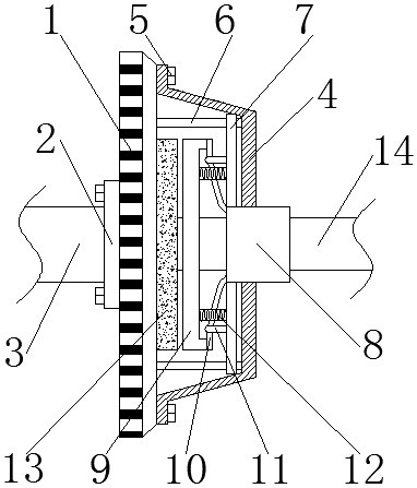
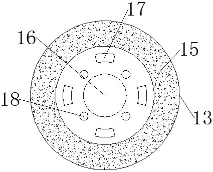
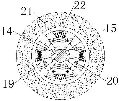
The assembly improved structure comprises a flywheel, the middle of the flywheel is fixedly connected with a power input shaft through a connecting base, the end, away from the power input shaft, of the flywheel is fixedly connected with a clutch cover, and a plurality of rivets are fixedly connected between the clutch cover and the flywheel. The upper ends of the rivets are fixedly connected with a gland, a friction disc is fixedly arranged at the end, close to the flywheel, in the clutch cover, a shaft hole is fixedly formed in the middle of the friction disc, and a friction plate is fixedly arranged on the periphery of the friction disc. The invention discloses an improved assembly structure on a mini-tiller clutch, which can avoid deviation when a clutch friction disc and a flywheel are separated, can enable the clutch to be separated quickly and accurately, reduces the failure rate of a mini-tiller, can inhibit fluctuation when power is transmitted, is more comfortable to use, and is worthy of popularization.

Description

technical field [0001] The invention relates to the technical field of clutches for micro-cultivators, in particular to an improved assembly structure on the clutches of micro-cultivators. Background technique [0002] With the development of science and technology, the degree of agricultural mechanization and automation has been greatly improved. Therefore, a large number of agricultural machinery have appeared. Among them, the micro-tiller is the most widely used machine in agriculture. The micro-tiller is widely used in plains. , mountainous areas, hilly dry land, paddy fields, orchards and other areas, solve the trouble that large agricultural machinery cannot enter the mountainous fields for farming, and it is the best choice for consumers to replace cattle farming. [0003] The existing micro-cultivator mainly controls the shifting and speed change through the clutch. The clutch assembly structure in the existing micro-cultivator is generally formed by directly assembl...

Claims


Application Information

Patent Timeline
IPC IPC(8): F16D13/44F16D13/58F16D13/64F16D13/71F16F15/123A01B71/00
CPCF16D13/44F16D13/58F16D13/585F16D13/644F16D13/71F16F15/1232A01B71/00Y02T10/62
Inventor 唐启兵
Owner 湘潭富民农业机械有限公司
Learn More