Organic waste gas thermodynamic catalytic oxidation device and use method

An organic waste gas, catalytic oxidation technology, applied in combustion methods, incinerators, lighting and heating equipment, etc., can solve the problems of unsatisfactory heat exchange effect, low work efficiency, dangerous use, etc., and achieve scientific and rational use methods and automation. Control and expand the effect of applications

Pending Publication Date: 2022-05-27
YANGZHOU UNIV
View PDF0 Cites 0 Cited by
  • Summary
  • Abstract
  • Description
  • Claims
  • Application Information

AI Technical Summary

Problems solved by technology

[0004] 1. Burners are used to heat up the organic waste gas to reach the oxidation temperature, and the fuel used by the burners is natural gas or diesel oil, etc., which inevitably uses special pipelines or oil storage tanks, which require professional operation and maintenance. maintenance, and its use is also quite dangerous
[0005] 2. The gas channel used for the catalytic oxidation of organic waste gas in the existing RCO technology has honeycomb features and is sprayed with a metal catalyst on the surface. Since it does not have a design for strengthening the contact between the gas and the channel wall, the effect of catalytic oxidation of organic waste gas is also slightly Inferior
[0006] 3. The ceramic regenerator used for air intake preheating in the existing RTO technology requires valve switching operation, and the work efficiency is not high. The tube and tube heat exchanger used for intake air preheating in the RCO technology has no heat storage function. Its heat transfer effect is also not satisfactory, neither of them has a design that integrates heat storage and heat transfer

Method used


Image

  • Organic waste gas thermodynamic catalytic oxidation device and use method
  • Organic waste gas thermodynamic catalytic oxidation device and use method
  • Organic waste gas thermodynamic catalytic oxidation device and use method

Examples


Embodiment Construction

[0039]The present invention will be further described below in conjunction with the accompanying drawings. Obviously, the described embodiments are some, but not all, embodiments of the present invention. Based on the embodiments of the present invention, all other embodiments obtained by those of ordinary skill in the art without creative efforts shall fall within the protection scope of the present invention.

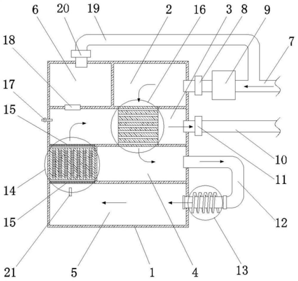
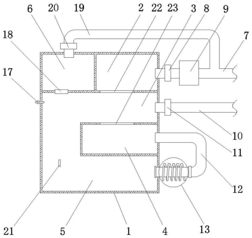
[0040] The structure of the organic waste gas thermal catalytic oxidation device provided by the present invention is as follows: figure 1 As shown, housing 1 , heat exchanger 16 , induction heating device 13 and gas turbulator 14 are included. The structure of shell 1 is as follows figure 2 shown. In this embodiment, a modular design is adopted. The cross section of the casing 1 is rectangular, and the interior is divided into 4 layers of chambers horizontally by partitions. There is a circulation warehouse inlet valve 18 in the lower baffle of the circulation w...


PUM


Abstract

The invention discloses an organic waste gas thermodynamic catalytic oxidation device and a use method. The device comprises a shell, a heat exchanger, an induction heating device and a gas turbulator, the shell comprises an air inlet bin, a preheating bin, a heating bin and a circulating bin which are arranged at intervals through partition plates. The air inlet bin is connected with the preheating bin through a heat exchanger; the heat exchanger is a cuboid, and a plurality of through holes which are arranged in a mutually perpendicular array mode are formed in the heat exchanger. The preheating bin is externally connected with a heating air inlet pipe, and the heating air inlet pipe is connected with the heating bin through an induction heating device. A gas turbulator is arranged in the heating bin, and the gas inlet end and the gas outlet end of the turbulator are each provided with a grating net used for sufficient reaction; a circulating bin air inlet valve is arranged between the heating bin and the circulating bin, and the other side is connected with an air outlet bin through a heat exchanger; the modular design is adopted, the heat exchanger structure can effectively save heating energy, the turbulator structure can enable gas to further fully react, and the heating unit also adopts electromagnetic heating, so that the device is more environment-friendly.

Description

technical field [0001] The invention relates to the technical field of organic waste gas treatment, and mainly relates to a thermal catalytic oxidation device for organic waste gas and a method for using the same. Background technique [0002] Organic waste gas usually refers to the volatile gas generated in the industrial production process, referred to as VOC, which is flammable, explosive, highly toxic, soluble in organic solvents, and difficult to handle. At present, organic waste gas treatment generally includes activated carbon adsorption, spray absorption and thermal combustion. Among them, activated carbon adsorption and spray absorption are essentially the transfer of pollutants, and it is not easy to process the adsorbed activated carbon and the absorbed solution. Thermal combustion produces water and carbon dioxide, and there is no pollution and no secondary treatment problems, so thermal combustion has become a good choice for organic waste gas treatment. [000...

Claims


Application Information

Patent Timeline
Patent Type & Authority Applications(China)
IPC IPC(8): F23G7/07F23G5/10F23G5/02F23G5/46F23G5/50
CPCF23G7/07F23G5/10F23G5/02F23G5/46F23G5/50F23G2204/204F23G2209/14
Inventor 张志高张露单杰沈茂松秦康生
Owner YANGZHOU UNIV
Why Eureka
Try Eureka