Experimental device for friction force research and use method thereof

An experimental device and friction technology, applied in the experimental field of friction research, can solve the problems of poor demonstration effect, inability to roll friction demonstration, large workload, etc., to achieve convenient operation, convenient observation and reading, and improved stability. Effect

Pending Publication Date: 2022-05-27
CHUZHOU VOCATIONAL & TECHN COLLEGE
View PDF1 Cites 0 Cited by
  • Summary
  • Abstract
  • Description
  • Claims
  • Application Information

AI Technical Summary

Problems solved by technology

[0005] The purpose of the present invention is to provide a kind of experimental device for friction research and its use method, to solve the above-mentioned background technology that can not demonstrate the direction of friction force and relative motion trend direction, can not intuitively and accurately demonstrate static friction force, maximum static friction force In the process of changing the sliding friction force, the rolling friction force cannot be demonstrated, and the experimental data needs to be manually calculated in the later stage to obtain the experimental results. The problem is that the workload is large and the demonstration effect is poor.

Method used


Image

  • Experimental device for friction force research and use method thereof
  • Experimental device for friction force research and use method thereof
  • Experimental device for friction force research and use method thereof

Examples


Embodiment 1

[0054] Example 1: The relationship between the magnitude of sliding friction and the roughness of the contact surface

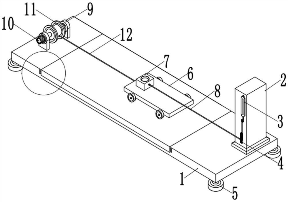
[0055] Under the condition that the pressure on the contact surface remains unchanged, use a different test plate 24 with a towel surface, cotton cloth surface or other materials such as rubber surface, iron surface, etc. to explore the relationship between the sliding friction force and the roughness of the contact surface. relation.

Embodiment 2

[0056] Example 2: The relationship between the magnitude of the sliding friction and the pressure on the contact surface

[0057] Under the condition that the surface of the test bench 1 remains unchanged, weights of different masses are added to the column block 7 to change the pressure on the contact surface, so as to explore the relationship between the sliding friction force and the pressure on the contact surface.

Embodiment 3

[0058] Example 3: The relationship between the magnitude of the sliding friction force and the relative motion speed

[0059] Under the condition that the pressure on the contact surface and the roughness of the contact surface remain unchanged, the speed of the motor 10 can be changed by selecting the play button and the fast-forward button, or the output voltage of the transformer can be adjusted to change the relationship between the flatbed trolley 6 and the column block 7. The speed of movement allows it to conduct several experiments at different speeds to explore the relationship between the magnitude of the sliding friction and the relative movement speed.


PUM


Abstract

The invention relates to the technical field of experiments for friction force research, in particular to an experimental device for friction force research and a use method thereof.The experimental device comprises a test board, a lug is welded to one end of the center of the outer wall of the top of the test board, and the interior of the lug is movably connected with a winding roller through a bearing; a motor in transmission connection with the winding roller is installed on the outer wall of one side of the lug through a bolt, a traction rope is wound on the outer side wall of the winding roller, a stand column is welded to the other end, away from the lug, of the top of the test table, and a dynamometer is fixedly installed at the top of the outer wall of one side of the stand column through a screw; and a side frame is welded under the stand column close to the dynamometer. The experimental device is convenient to operate, testers can independently operate the experimental device, observation and reading are facilitated, the dynamometer and the whole experimental device always face the testers in the experimental process, the dynamometer and the column block are always relatively static, reading is stable, and observation and reading are facilitated.

Description

technical field [0001] The invention relates to the technical field of experiments for friction force research, in particular to an experimental device for friction force research and a method for using the same. Background technique [0002] Friction refers to the force that hinders the relative motion (or relative motion trend) of an object, and its direction is opposite to the direction of the relative motion (or relative motion trend) of an object; friction is divided into three types: static friction, rolling friction, and sliding friction. The size of the sliding friction force is related to the roughness of the contact surface and the size of the pressure. The greater the pressure, the rougher the contact surface of the object, and the greater the sliding friction force generated. [0003] Chinese Patent No. CN101236707B relates to a plane, slope dynamic and static friction demonstration instrument, which belongs to the field of physics teaching demonstration instrum...

Claims


Application Information

Patent Timeline
IPC IPC(8): G09B23/10G01L1/04G01N19/02
CPCG09B23/10G01L1/04G01N19/02
Inventor 梁金荣王善勤汪蓓蓓宋园
Owner CHUZHOU VOCATIONAL & TECHN COLLEGE
Why Eureka
Try Eureka