Machining device for building construction warning board
A technology for building construction and processing devices, which is applied to injection devices, photovoltaic power generation, etc., can solve the problems of reducing the processing efficiency and quality of the warning signs, increasing the complexity of the disassembly of the fixture, and inconvenient to limit the position of warning signs of different shapes. Processing efficiency and delivery quality, increased flexibility and stability, and improved usability
- Summary
- Abstract
- Description
- Claims
- Application Information
AI Technical Summary
Problems solved by technology
Method used
Image

Examples
Embodiment Construction
[0028] The following will clearly and completely describe the technical solutions in the embodiments of the present invention with reference to the accompanying drawings in the embodiments of the present invention. Obviously, the described embodiments are only some, not all, embodiments of the present invention. Based on the embodiments of the present invention, all other embodiments obtained by persons of ordinary skill in the art without making creative efforts belong to the protection scope of the present invention.
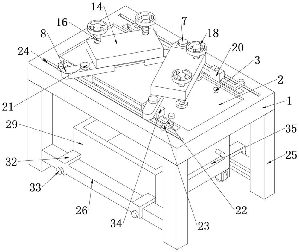
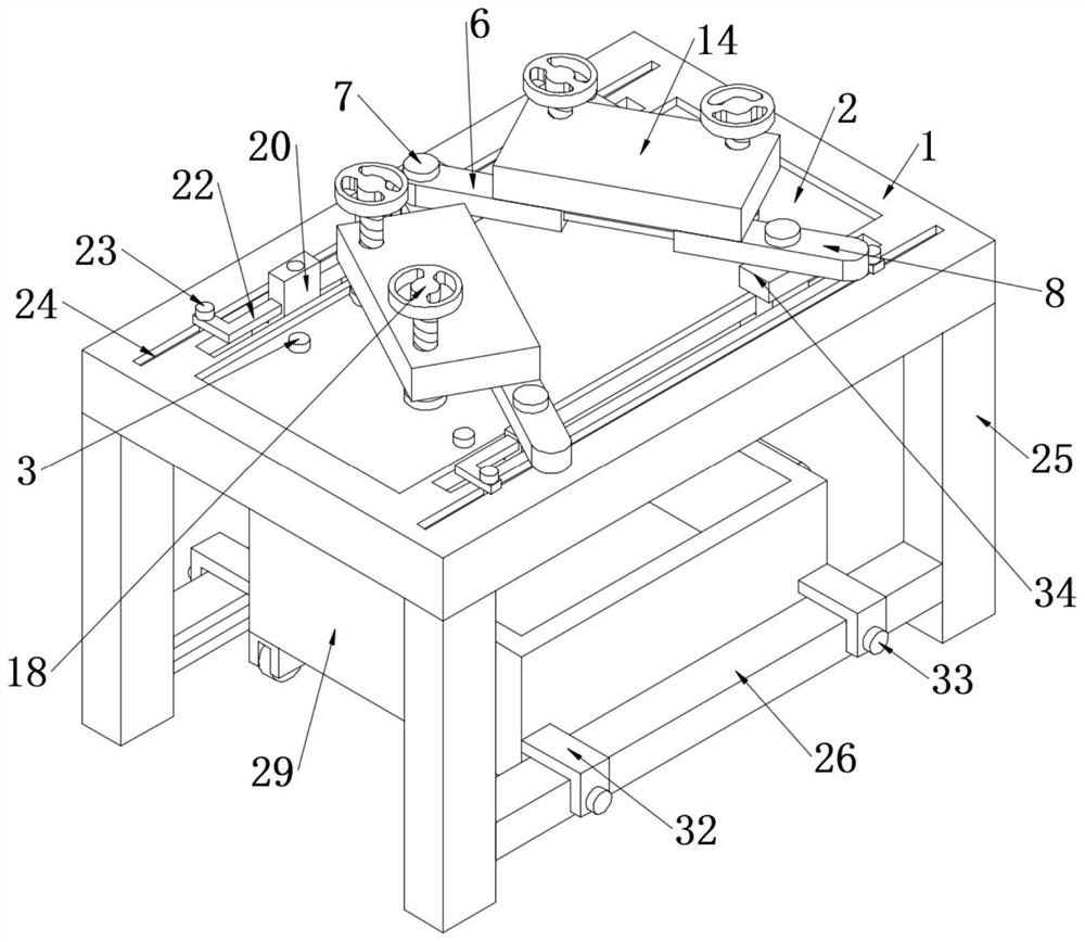
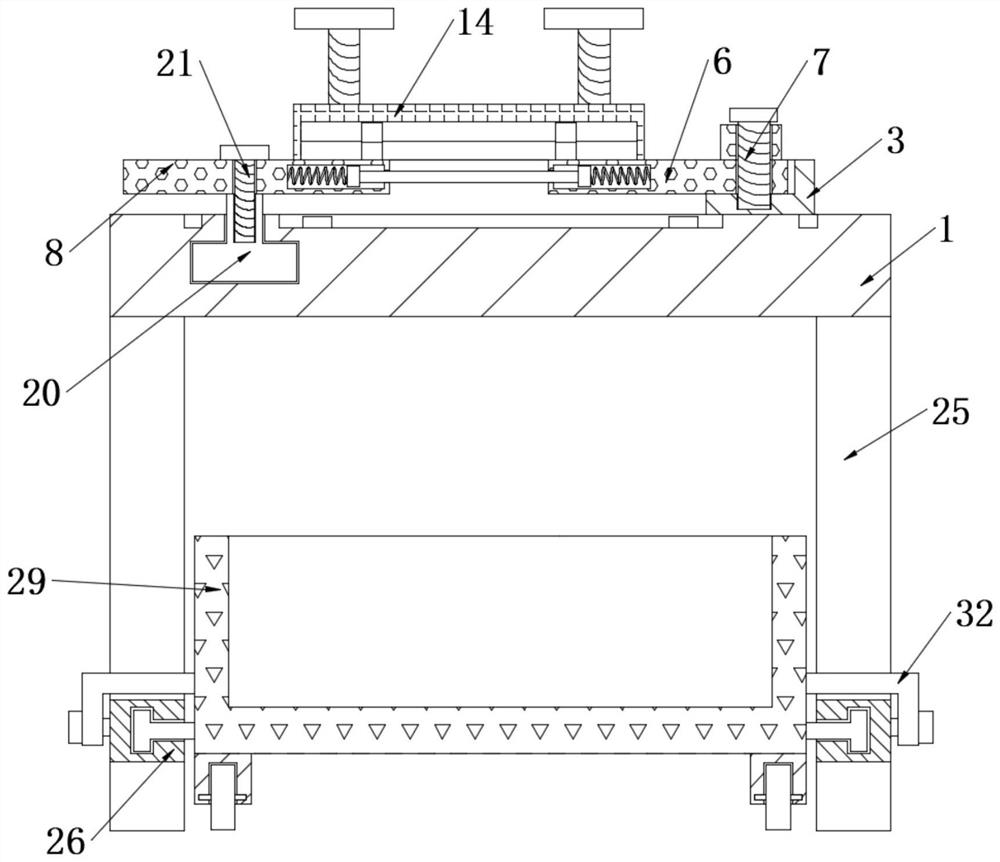
[0029] The present invention provides such Figure 1-8 The shown processing device for a construction warning sign includes a workbench 1. The cross-sectional shape of the workbench 1 is rectangular, which is convenient for the fixed installation of the fixing seat 4. One side of the upper surface of the workbench 1 is fixedly connected with the fixing seat 4. The fixing seat 4 is provided with an installation groove 5, and the top view section shape of the in...
PUM
 Abstract
Description
Claims
Application Information