Multi-workbench grinding center
A grinding center and multi-table technology, which is applied in the direction of grinding/polishing equipment, grinding machine parts, grinding machines, etc., can solve the problems of grinding head standby and low processing efficiency, so as to improve processing efficiency and occupy a small area , The effect of speeding up the production tempo
- Summary
- Abstract
- Description
- Claims
- Application Information
AI Technical Summary
Problems solved by technology
Method used
Image

Examples
Embodiment 1
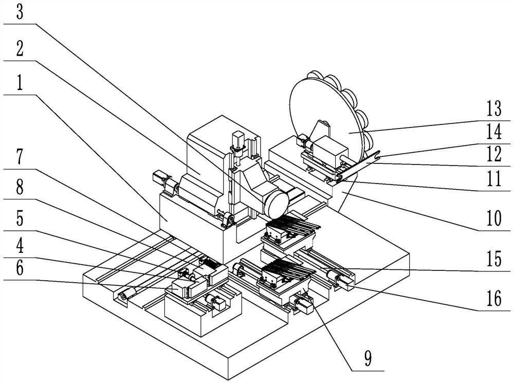
[0035] like figure 1 As shown, a multi-table 9 grinding center has:
[0036] A grinding table 1 that can move freely in the length direction, the grinding table 1 is provided with a column 2 that can move freely in the width direction, and the column 2 is provided with a grinding head 3 that can move freely in the height direction;
[0037] A dresser, the dresser includes a disc 5 single-point dresser 6 and a roller dresser 8;
[0038] Two workbenches 9 arranged along the length for positioning workpieces;
[0039] Tool changing device, the tool changing device is arranged at one end of the length direction of the grinding center, and the tool changing device includes a tool changing plate 12 that can move freely in the length and width directions and a grinding wheel storage plate 13 that is rotatably connected to the bed of the grinding center. The plate 12 is strip-shaped, and the center line of the knife changing plate 12 is arranged along the width direction and rotates...
Embodiment 2
[0047] The difference between this embodiment and embodiment 1 is:
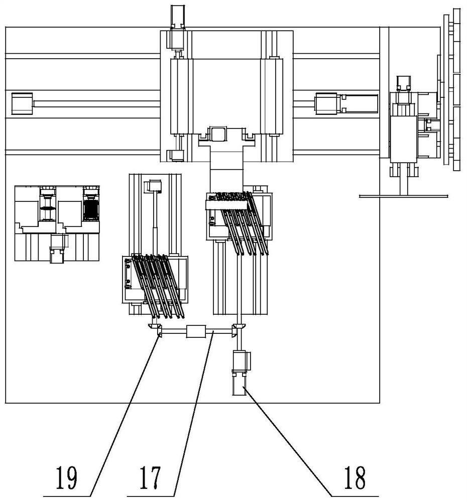
[0048]like figure 2 As shown, the driving mode of the workbench 9 is different from that of Embodiment 1. The workbench 9 is installed on the bed of the grinding center through the linear guide rail 11, and the workbench 9 is driven by the screw slider pair. 15 is connected through a transition shaft 17 transmission, the screw thread direction of two leading screws 15 is opposite, and the corresponding leading screw 15 transmission connection of two workbenches 9 is connected with drive motor 18. The leading screw and the transition shaft are connected through a bevel gear 19 transmission.
Embodiment 3
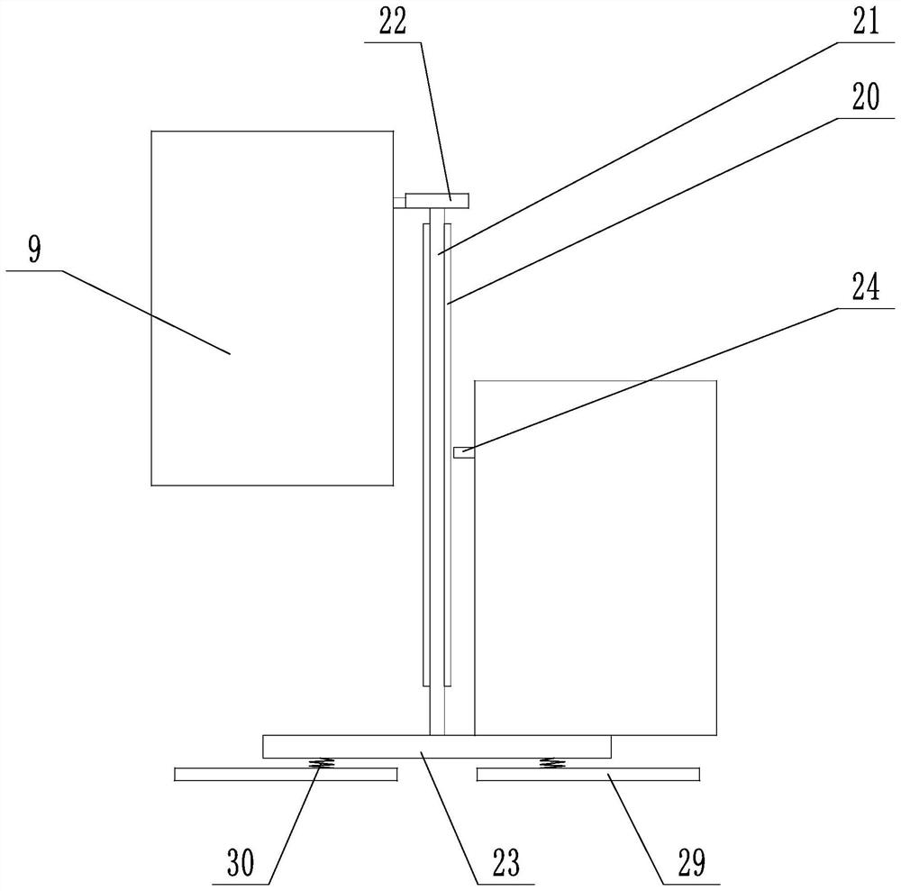
[0050] like image 3 , 4 Shown, present embodiment also has on the basis of embodiment 1:
[0051] Alternate locking parts are provided between the two worktables 9, and the alternate locking parts include locking chute 20 bevel gears 19 arranged between the two workbenches 9, and locking guides are provided on the locking chute 20 bevel gears 19. Rod 21, the two ends of the locking guide rod 21 protrude from the locking chute 20 and the bevel gear 19 and are respectively provided with a locking positive hook 22 and an interference plate 23 at both ends. Reverse hook 24, locking guide rod 21 is fixedly connected vertically arranged sleeve 25 at one end of locking positive hook 22, and locking positive hook 22 is vertically inserted in sleeve 25 and its two ends pass through, lock A spring 26 is arranged between the tight positive hook 22 and the sleeve 25, and the spring 26 drives the locking positive hook 22 to move downward. The bottom of the hook 22 is provided with a be...
PUM
 Abstract
Description
Claims
Application Information
 - R&D Engineer
- R&D Manager
- IP Professional
- Industry Leading Data Capabilities
- Powerful AI technology
- Patent DNA Extraction
Browse by: Latest US Patents, China's latest patents, Technical Efficacy Thesaurus, Application Domain, Technology Topic.
© 2024 PatSnap. All rights reserved.Legal|Privacy policy|Modern Slavery Act Transparency Statement|Sitemap