Bamboo mat production punching machine with guide structure
A guide structure, punching machine technology, applied in wood stamping, mechanical equipment, sugarcane machining and other directions, can solve the problem of processing material limit and other problems, and achieve the effect of strengthening friction, preventing offset, and limit fixing and stable.
- Summary
- Abstract
- Description
- Claims
- Application Information
AI Technical Summary
Problems solved by technology
Method used
Image
Examples
specific Embodiment 1
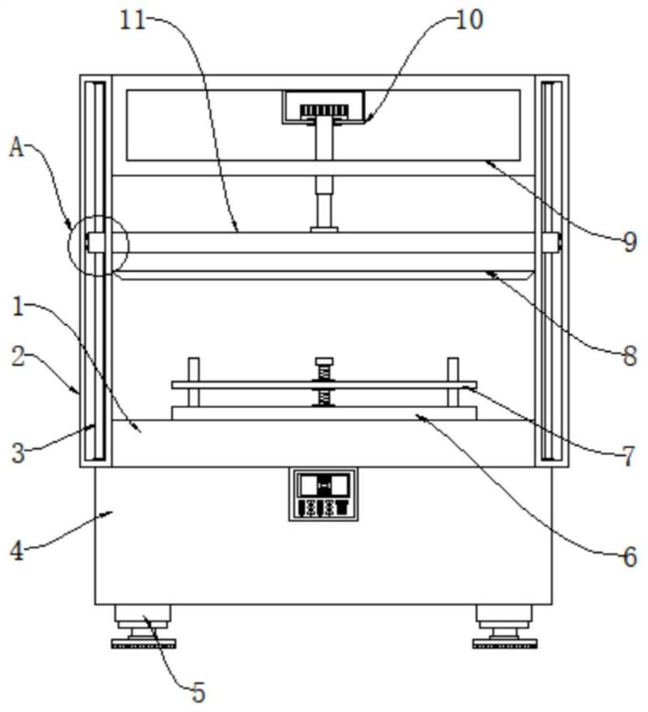
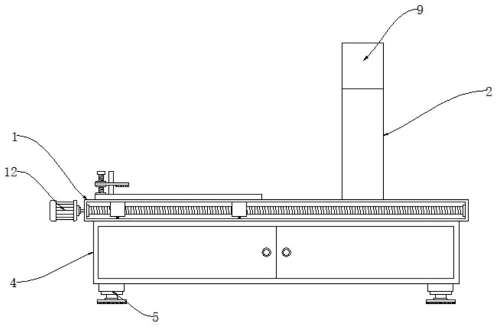
[0033] Specific embodiment one, at first between the limiting plate 701 and the moving plate 6 are connected by the threaded rod 702 and the positioning rod 703, the threaded rod 702 and the limiting plate 701 form a threaded connection, twisting the threaded rod 702 can drive and form the screw thread The connected limiting plate 701 rises and falls, and when the limiting plate 701 descends, the material can be sandwiched between the limiting plate 701 and the moving plate 6 to limit the material. The anti-skid pad 704 at the bottom of the limiting plate 701 can strengthen the limiting plate The frictional force of 701 makes the limit fixing of the limit plate 701 more stable, and the positioning rod 703 runs through the limit plate 701, and the positioning rod 703 can guide the limit plate 701 to prevent the limit plate 701 from shifting;
[0034]The inside of workbench 1 is equipped with moving mechanism 12, and moving mechanism 12 comprises servo motor 1201, screw rod 1202 ...
specific Embodiment 2
[0035] Specific embodiment two, at first servomotor 1201 work just can drive screw rod 1202 to rotate, and the block body of screw rod 1202 and moving plate 6 bottoms forms screw connection, and screw rod 1202 just does not drive moving plate 6 to move, and moving plate 6 moves just can Drive the material at its top to move, so that the material can automatically move to the bottom of the blade 8 for cutting. The connecting rod 1203 runs through the moving plate 6, and the connecting rod 1203 can guide the moving plate 6. After the material moves to the bottom of the blade 8, the hydraulic pressure When the cylinder 10 works, it can drive the fixed block 11 up and down, and the fixed block 11 can drive the blade 8 up and down, and the blade 8 can be lifted up and down to punch the material;
[0036] Supports 2 are installed on both sides of the workbench 1, and the inside of the support 2 is provided with a guide structure 3. The guide structure 3 includes guide grooves 301, gu...
specific Embodiment 3
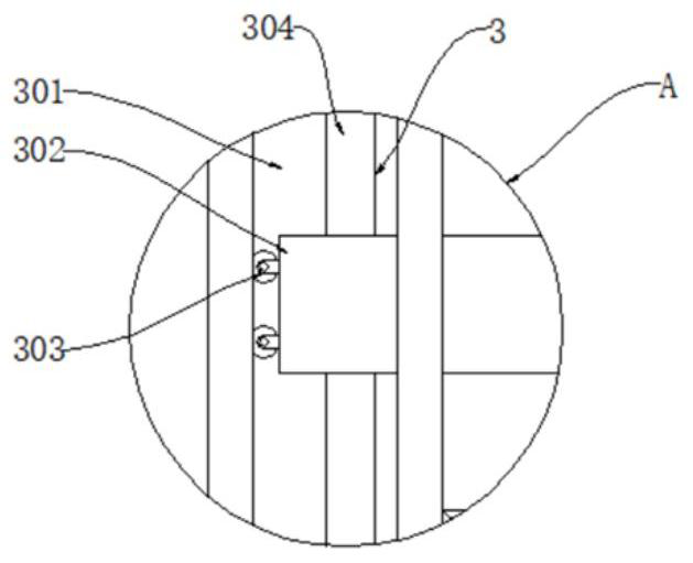
[0037] Specific embodiment three, at first the guide groove 301 and the guide block 302 on both sides of the fixed block 11 cooperate with each other, the guide wheel 303 on one side of the guide block 302 can make the fixed block 11 move more smoothly, the guide rod 304 runs through the guide block 302, Guide rod 304 can guide guide block 302, prevents guide block 302 from dismounting offset, and guide block 302 and guide groove 301 cooperate just can guide fixed block 11, prevent that fixed block 11 from shifting when lifting, to fixed block 11 Guide just can guide blade 8;
[0038] A casing 9 is installed on the top of the bracket 2, and a hydraulic cylinder 10 is installed inside the casing 9. The model of the hydraulic cylinder 10 can be HSG. A fixed block 11 is installed at the bottom of the hydraulic cylinder 10, and a blade 8 is installed at the bottom of the fixed block 11. .
PUM
 Abstract
Description
Claims
Application Information
 - R&D
- Intellectual Property
- Life Sciences
- Materials
- Tech Scout
- Unparalleled Data Quality
- Higher Quality Content
- 60% Fewer Hallucinations
Browse by: Latest US Patents, China's latest patents, Technical Efficacy Thesaurus, Application Domain, Technology Topic, Popular Technical Reports.
© 2025 PatSnap. All rights reserved.Legal|Privacy policy|Modern Slavery Act Transparency Statement|Sitemap|About US| Contact US: help@patsnap.com


