
Thermal management system control method and device

A technology of a thermal management system and a control method is applied in the field of a thermal management system control method and device, and can solve problems such as discomfort for drivers and passengers, sudden change in the temperature of an air conditioner outlet of a passenger cabin, affecting the NVH performance of the whole vehicle, etc.

Pending Publication Date: 2022-05-31
GAC AION NEW ENERGY AUTOMOBILE CO LTD
View PDF0 Cites 0 Cited by
  • Summary
  • Abstract
  • Description
  • Claims
  • Application Information

AI Technical Summary

Problems solved by technology

However, in practice, it is found that the existing method will cause the temperature mutation of the air conditioner outlet in the passenger compartment, which will cause discomfort to the driver and passengers. At the same time, it is also prone to high-frequency opening and closing noise of the valve, which will affect the NVH performance of the vehicle.

Method used


Image

  • Thermal management system control method and device
  • Thermal management system control method and device
  • Thermal management system control method and device

Examples


Embodiment 1

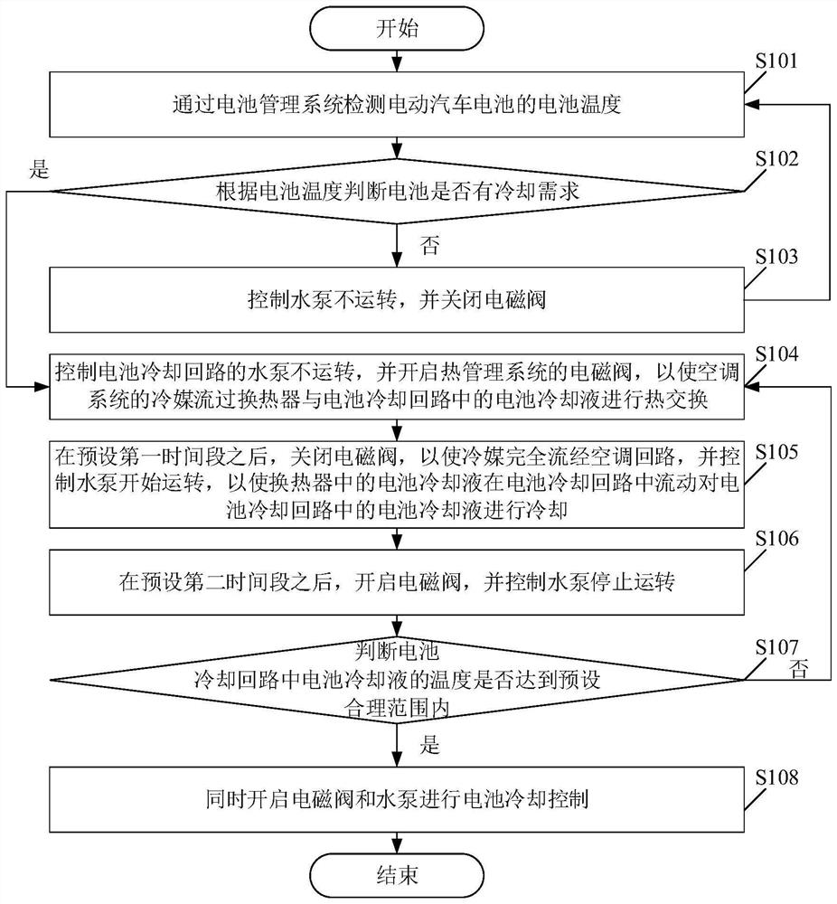
[0042] Please see figure 1 , figure 1 A schematic flowchart of a method for controlling a thermal management system is provided for an embodiment of the present application. Wherein, the thermal management system control method includes:

[0043] S101. Detect the battery temperature of the electric vehicle battery through the battery management system.

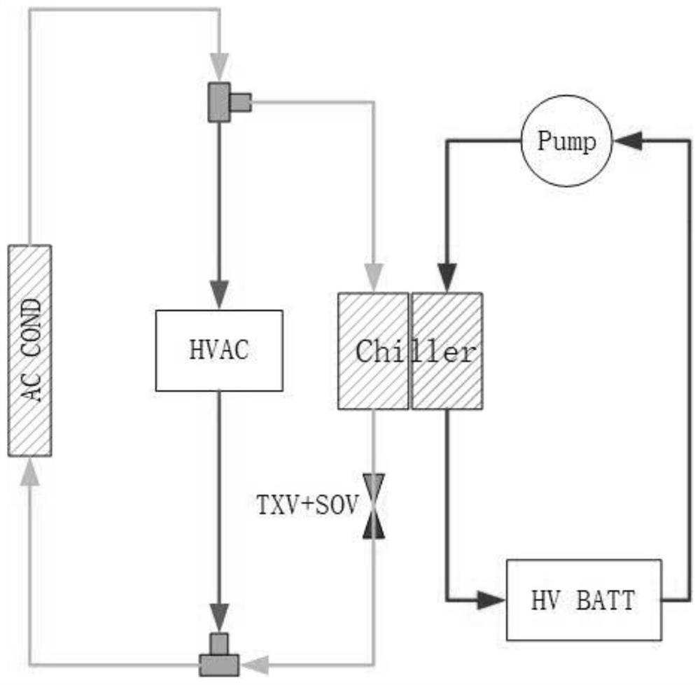
[0044] In the embodiment of the present application, the method belongs to the technical field of electric vehicle thermal management system control, and is a coordinated control method applied to a common thermal management system architecture (solenoid valve and thermal expansion valve).

[0045] In this embodiment of the present application, the subject of execution of the method may be a thermal management system control device. Specifically, the thermal management system control device may run on a computer, server, smart phone, tablet computer, and other devices. In this embodiment, Do not make any restrictions.

[0...

Embodiment 2

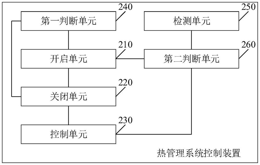
[0067] Please see figure 2 , figure 2 It is a schematic structural diagram of a thermal management system control device provided in an embodiment of the present application. like figure 2 As shown, the thermal management system control device includes:

[0068] The opening unit 210 is used to control the water pump of the battery cooling circuit not to operate when it is detected that the battery of the electric vehicle needs to be cooled, and to open the solenoid valve of the thermal management system so that the refrigerant of the air conditioning system flows through the heat exchanger and the battery cooling circuit The battery coolant in the battery is exchanged for heat;

[0069] The closing unit 220 is configured to close the solenoid valve after a preset first time period, so that the refrigerant can completely flow through the air conditioning circuit;

[0070] The control unit 230 is used to control the water pump to start running, so that the battery coolant...


PUM


Abstract

The thermal management system control method comprises the steps that when it is detected that a battery of an electric vehicle needs to be cooled, a water pump of a battery cooling loop is controlled not to operate, and an electromagnetic valve of a thermal management system is started, so that a refrigerant of an air conditioning system flows through a heat exchanger to conduct heat exchange with battery cooling liquid in the battery cooling loop; after a preset first time period, the electromagnetic valve is closed, so that the refrigerant completely flows through the air conditioner loop, and the water pump is controlled to start to operate, so that the battery cooling liquid in the heat exchanger flows in the battery cooling loop to cool the battery cooling liquid in the battery cooling loop; opening the electromagnetic valve after a preset second time period, and controlling the water pump to stop running; when the temperature of the battery cooling liquid in the battery cooling loop reaches the preset reasonable range, the electromagnetic valve and the water pump are started at the same time to conduct battery cooling control, the temperature impact on an air conditioning system of a passenger compartment can be reduced during battery cooling, high-frequency opening and closing noise of the valve can be avoided, and the NVH performance of the whole vehicle is guaranteed.

Description

technical field [0001] The present application relates to the technical field of automobiles, in particular, to a method and device for controlling a thermal management system. Background technique [0002] At present, electric vehicles, as new energy vehicles, have received widespread attention from all walks of life. During the operation of electric vehicles, the temperature of the battery cells will be maintained within a certain temperature range through the cooling system of the vehicle, so that the batteries can be charged and discharged more normally. . In the existing electric vehicles, the control method of the thermal management system is usually coupled with the passenger compartment air conditioning system through a heat exchanger. swap, thereby cooling the battery. However, in practice, it has been found that the existing method will cause sudden changes in the temperature of the air-conditioning outlet in the passenger compartment, causing discomfort to the d...

Claims


Application Information

Patent Timeline
IPC IPC(8): B60L58/26B60H1/00B60L58/10H01M10/613H01M10/625H01M10/633H01M10/635H01M10/6556H01M10/6567H01M10/663
CPCB60L58/26B60H1/00278B60L58/10H01M10/613H01M10/625H01M10/633H01M10/635H01M10/6556H01M10/6567H01M10/663B60H2001/00307Y02T10/70
Inventor 欧光宇覃威铭郑俊军周才
Owner GAC AION NEW ENERGY AUTOMOBILE CO LTD
Learn More