
Concrete pavement leveling device for highway construction

A technology for concrete pavement and leveling device, which is applied to roads, roads, road repair and other directions, can solve the problems of maintenance burden, prone to cracks, unevenness, etc., and achieve the effects of easy disassembly and replacement, improved practicability, and simple operation.

Inactive Publication Date: 2022-05-31
金鑫民 +5
View PDF0 Cites 0 Cited by
  • Summary
  • Abstract
  • Description
  • Claims
  • Application Information

AI Technical Summary

Problems solved by technology

[0002] During long-term use, roads are often crushed and potholes appear. In conventional treatment methods, such as asphalt concrete pavement, potholes are often filled with fillers, and more raw materials are usually prefilled. , and then use heavy equipment such as rolling rollers to flatten and compact it. However, since the rolling rollers are generally large in size, the area under pressure is relatively large during compaction, and there may be a supporting effect on the original intact road surface, resulting in The compaction effect of the newly filled area is poor or uneven, and it is flat and not solid, and it is easy to be damaged again in a short time; the rolling roller mainly uses vertical downward force to compact and flatten the road surface, then For the vertical boundary of potholes, the compaction effect of new material and old material is very poor, and new material and old material cannot be well compacted and combined. If the combination of the two is not good, cracks are likely to appear. The above defects are likely to cause damage to the repaired road section. Rapid damage, greater burden on repairs

Method used


Image

  • Concrete pavement leveling device for highway construction
  • Concrete pavement leveling device for highway construction
  • Concrete pavement leveling device for highway construction

Examples


Embodiment Construction

[0024] The present invention will be further described in detail below in conjunction with the accompanying drawings and specific embodiments.

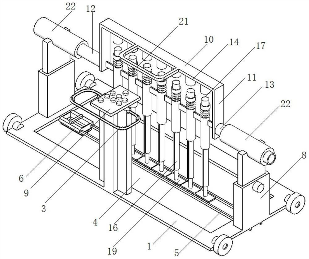
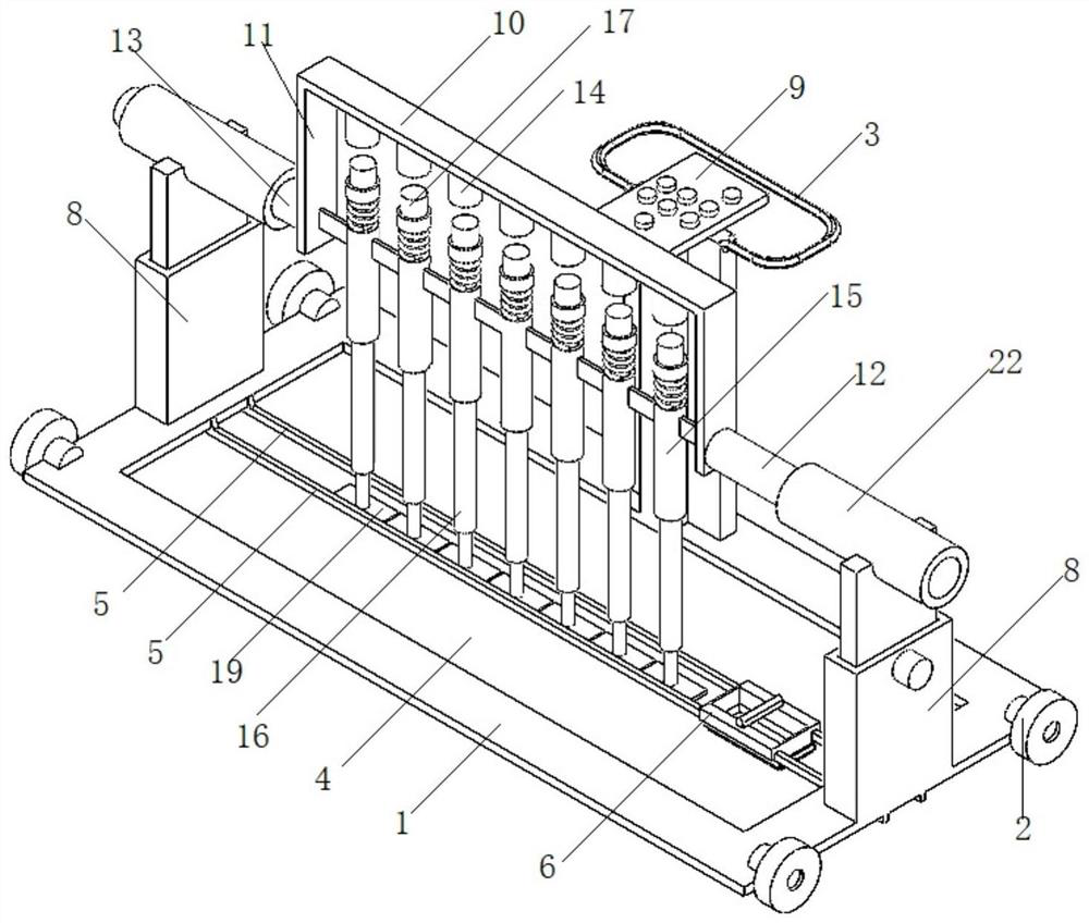
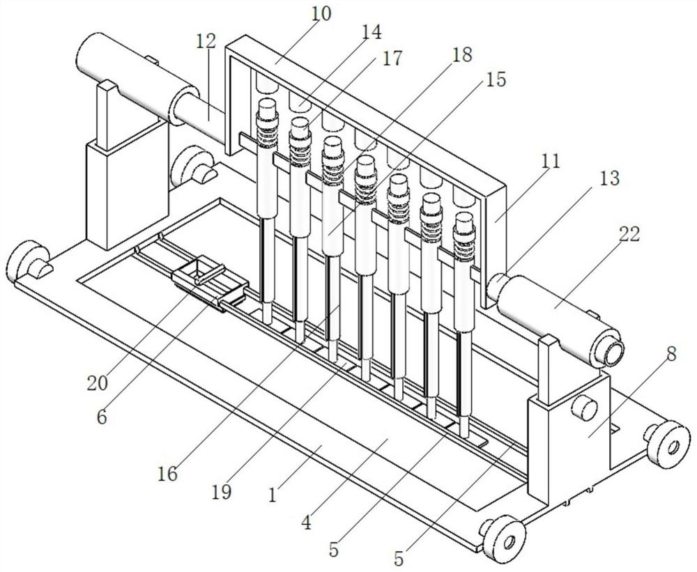
[0025] Such as Figure 1-9 As shown, a concrete pavement leveling device for highway construction includes a base plate 1; a plurality of wheels 2 are respectively installed on the left and right sides of the base plate 1; a hand push frame 3 is fixed on the rear side of the upper end of the base plate 1; 4. Two parallel sliding rails 5 are fixedly installed in the middle of the operation window 4, and the sliding rails 5 are arranged along the left and right directions; there are at most two packing frames 6 slidingly arranged between the two sliding rails 5; the packing frame 6 is a square frame The packing frame 6 slides left and right between the two slide rails 5; the ring surface of the lower end of the packing frame 6 is fixed with a square-shaped rubber scraper 7; the left and right sides of the upper end of the bottom plate 1...


PUM


Abstract

The invention discloses a concrete pavement leveling device for highway construction, and relates to the technical field of highway construction. The device comprises a bottom plate, at most two filling frames are arranged between the two sliding rails in a sliding manner; a pavement flattening mechanism is arranged between the two positioning pipes; the pavement flattening mechanism comprises a mounting plate; a plurality of electromagnets are uniformly fixed at the lower end of the mounting plate in the left-right direction at equal intervals; a plurality of vertical guide pipes are fixedly arranged below the electromagnet side by side; a magnetic pressing rod device is mounted in each guide pipe in an up-down sliding manner; the magnetic pressure rod device comprises a push rod; permanent magnets are fixed at the upper ends of the push rods. The device has the beneficial effects that the pavement compaction effect is more finely checked, the pavement leveling work is completed, new materials and old materials at the boundary can be combined more compactly and better, and the construction quality is improved.

Description

technical field [0001] The invention relates to the technical field of road construction. Background technique [0002] During long-term use, roads are often crushed and potholes appear. In conventional treatment methods, such as asphalt concrete pavement, potholes are often filled with fillers, and more raw materials are usually prefilled. , and then use heavy equipment such as rolling rollers to flatten and compact it. However, since the rolling rollers are generally large in size, the area under pressure is relatively large during compaction, and there may be a supporting effect on the original intact road surface, resulting in The compaction effect of the newly filled area is poor or uneven, and it is flat and not solid, and it is easy to be damaged again in a short time; the rolling roller mainly uses vertical downward force to compact and flatten the road surface, then For the vertical boundary of potholes, the compaction effect of new material and old material is ver...

Claims


Application Information

Patent Timeline
Patent Type & Authority Applications(China)
IPC IPC(8): E01C19/35E01C23/09E01C19/48B08B1/00
CPCE01C19/35E01C23/0966E01C19/4853B08B1/165Y02A30/60
Inventor 金鑫民金鑫王佳佳李志超吴彬杨凯婷
Owner 金鑫民
Learn More