
Novel hybrid excitation asynchronous starting permanent magnet synchronous motor stator and rotor structure

A technology of permanent magnet synchronous motor and mixed excitation, which is applied in the direction of magnetic circuit shape/style/structure, motor, and magnetic circuit rotating parts, etc. Low power density and other issues, achieve the effects of small cogging torque, shortened starting time, and easy magnetization

Pending Publication Date: 2022-05-31
HARBIN UNIV OF SCI & TECH
View PDF0 Cites 0 Cited by
  • Summary
  • Abstract
  • Description
  • Claims
  • Application Information

AI Technical Summary

Problems solved by technology

[0003] Permanent magnet synchronous motors can be divided into surface mount type and built-in type according to their rotor structure. Surface mount type permanent magnet synchronous motors have relatively small torque ripple and relatively low power density, while built-in permanent magnet synchronous motors The torque is relatively large, but the built-in motor has a large magnetic flux leakage, the air-gap flux density of the motor is relatively poor, and the harmonic content is relatively high. Therefore, it is necessary to improve the structure of the existing asynchronous starter permanent magnet synchronous motor.

Method used


Image

  • Novel hybrid excitation asynchronous starting permanent magnet synchronous motor stator and rotor structure
  • Novel hybrid excitation asynchronous starting permanent magnet synchronous motor stator and rotor structure
  • Novel hybrid excitation asynchronous starting permanent magnet synchronous motor stator and rotor structure

Examples


Embodiment Construction

[0016] The present invention will be further described in detail below with reference to the accompanying drawings and specific embodiments.

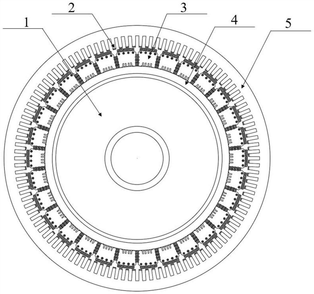
[0017] refer to figure 1 As shown in the figure, a 30-pole 108-slot asynchronous starting permanent magnet synchronous motor is used for design. The motor structure is that the stator is outside and the rotor is inside. The windings are double-layer windings, which are installed on the stator teeth. , There are four circular holes with a radius of 5mm on the top of the rotor pole for placing damping bars, so as to realize the self-starting function of the motor.

[0018] refer to figure 1 As shown, for the stator: each stator tooth top is installed with a magnet-adjusting block, which can convert the stator teeth of the motor into magnetic teeth, which can increase the torque density of the motor and shorten the starting time.

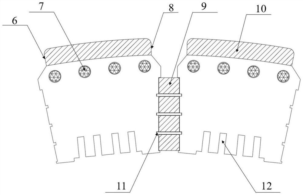
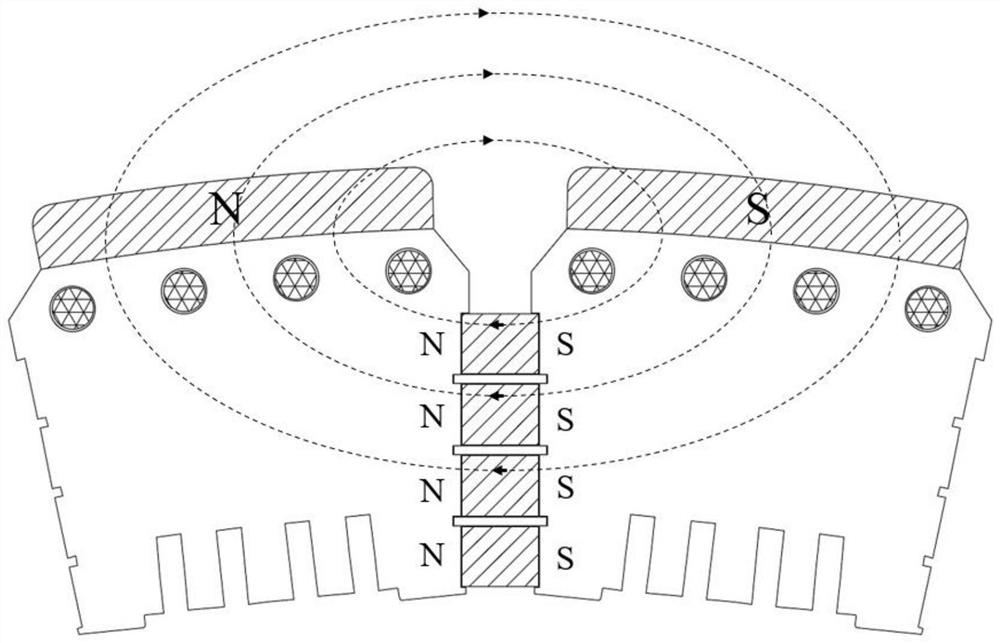
[0019] refer to figure 2 As shown, for the rotor: there are three equal-sized rectangular aluminum alloy ...


PUM


Abstract

The invention relates to a novel hybrid excitation asynchronous starting permanent magnet synchronous motor stator and rotor structure, and belongs to the technical field of motor structures. A motor body comprises a stator, a rotor magnetic pole, a damping bar, a magnetic isolation sleeve and a permanent magnet, and a 30-pole 108-slot motor structure with the stator arranged outside and the rotor arranged inside is adopted; the stator is composed of stator teeth and a stator yoke, the top of the teeth is provided with an adjustable magnet, the torque density of the motor can be increased, and the starting time of the motor is shortened. Rotor magnetic poles are circumferentially distributed on the inner side of the stator at equal intervals, four built-in permanent magnets are arranged among the magnetic poles, and a surface-mounted permanent magnet is arranged at the top of the rotor magnetic poles, so that the eddy current loss of the motor can be reduced, and the air gap flux density harmonic amplitude can be weakened; the bottoms of the magnetic poles are provided with rectangular notches, so that the tangential flux density of the motor is reduced, and the heat dissipation effect of the motor is improved.

Description

technical field [0001] The invention relates to the technical field of motor structures, in particular to a novel hybrid excitation asynchronous start permanent magnet synchronous motor stator and rotor structure. Background technique [0002] Asynchronous starting permanent magnet synchronous motor is to place permanent magnets in the iron core of three-phase induction motor, and rely on the asynchronous torque generated by the squirrel-cage rotor winding to realize the starting; compared with three-phase induction motors, the outstanding advantages of asynchronous starting permanent magnet synchronous motors are high Efficiency, high power factor and wider economic scope; my country is a big country of rare earths, and the output of rare earth permanent magnets ranks first in the world with rich rare earth resources, which has great advantages for vigorously developing permanent magnet synchronous motors. [0003] Permanent magnet synchronous motor can be divided into surfa...

Claims


Application Information

Patent Timeline
IPC IPC(8): H02K1/18H02K1/274H02K1/276H02K1/278H02K1/32
CPCH02K1/185H02K1/274H02K1/2773H02K1/278H02K1/32Y02T10/64
Inventor 戈宝军张梦娜范家成
Owner HARBIN UNIV OF SCI & TECH
Learn More