Multi-angle head supporting traction device

A traction device, multi-angle technology, applied in fractures, medical science, etc., can solve the problem that the traction frame cannot rotate

Active Publication Date: 2022-06-03
苏州夏橙智能科技有限公司
View PDF8 Cites 0 Cited by
  • Summary
  • Abstract
  • Description
  • Claims
  • Application Information

AI Technical Summary

Problems solved by technology

[0004] In order to solve the deficiencies of the prior art, the purpose of the present invention is to provide a multi-angle head support and traction device, which can achieve multiple angles of traction to the patient's head, and can solve the problem of traditional fixation when the patient changes from a supine position to a prone position. The problem that the traction frame cannot rotate

Method used


Image

  • Multi-angle head supporting traction device
  • Multi-angle head supporting traction device
  • Multi-angle head supporting traction device

Examples


Embodiment 1

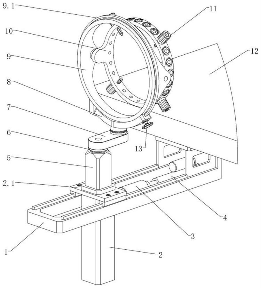
[0034] Embodiment 1: The retainer 10 is provided with a plurality of threaded holes 10.1 at equal intervals in the circumferential direction, and suitable positioning points can be adopted according to the actual conditions of different patients, so that the four skull nails 20 can fix the patient's head.

Embodiment 2

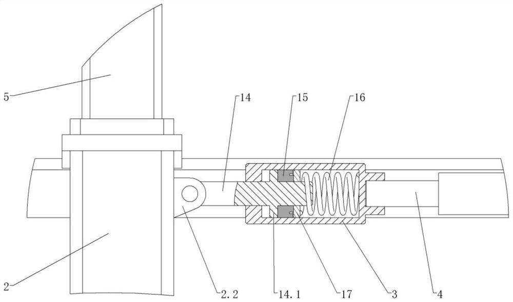
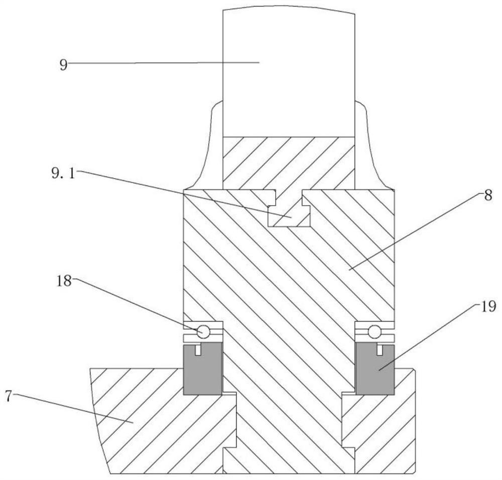
[0035] Embodiment 2: The holder 10 has six spatial degrees of freedom, wherein the rotational connection between the holder 10 and the turret 9 constitutes the horizontal axis of freedom, the rotatable connection between the turret 9 and the chute frame 8 constitutes the vertical axis of freedom, and the chute The frame 8 and the yaw arm 7 are rotatably connected to form the degree of freedom of vertical axis rotation. The lifting action of the lifting column 5 constitutes the degree of freedom of vertical axis movement. The forward and backward movement of the guide cylinder 2 constitutes the degree of freedom of vertical axis movement. The rotational connection constitutes the freedom of movement of the transverse axis; the abundant degrees of freedom enable the cage 10 to achieve multi-angle traction on the patient's head.

Embodiment 3

[0036] Embodiment 3: The electric cylinder 4 drives the guide cylinder 2 to move backward so that the holder 10 can pull the patient's head; when the horizontal swing arm 7 is in the longitudinal state and the center of the turret 9 is at the same height as the center of the patient's head, it can be To achieve longitudinal axis traction on the patient's head; when the swing arm 7 is in a longitudinal state and the center of the turret 9 is higher than the center of the patient's head, it can achieve upward traction on the patient's head; when the swing arm 7 is in a longitudinal state and rotates When the center of the frame 9 is lower than the center of the patient's head, the patient's head can be pulled downward; when the yaw arm 7 is rotated to the left and positioned, the holder 10 can be moved to the left and the rotatable frame 9 is clockwise. Deflection, so as to achieve leftward traction on the patient's head; when the yaw arm 7 is rotated to the right and positioned,...


PUM


Abstract

A supporting frame is fixedly connected with an operating table, a guide cylinder is installed on the supporting frame and can move front and back, a spring cylinder is installed on the front side of the guide cylinder through a push rod, and a spring, a gasket and a first pressure sensor are sequentially and coaxially installed in the spring cylinder from front to back; the electric cylinder installed on the front side of the spring barrel can push the spring barrel to move, the traction barrel can apply pushing force to the push rod through the spring to push the guide barrel to move so as to achieve traction of the head of a patient, the lifting column can move up and down and be positioned, and the motor is installed at the upper end of the lifting column and can drive the transverse swing arm to rotate horizontally. The sliding groove frame is rotationally connected with the front end of the transverse swing arm, the rotating frame is rotationally installed at the upper end of the sliding groove frame and can be locked through the locking wheel, the holder has six spatial freedom degrees and is rotationally installed at the front end of the rotating frame, the holder can be connected with the head of a patient through a plurality of skull nails, and the torsion column and the skull nails can be coaxially installed in a nested mode. And the skull nail cannot loosen and fall off.

Description

technical field [0001] The invention relates to the technical field of medical devices, in particular to a multi-angle head support and traction device. Background technique [0002] With the development of society and the progress of human beings, there are more and more patients with cervical spine injuries caused by traffic accidents and falls from high altitudes. Dislocation and spinal cord injury are life-threatening and the possibility of high paraplegia at any time; as we all know, cervical spine surgery is difficult and high-risk, and requires very high requirements for each operation. In severe cases, the patient will die quickly. [0003] Head traction is the first choice for the clinical treatment of cervical spine fractures and dislocations, especially for patients with spinal cord injury. It is also an important means of preoperative and intraoperative traction and reduction. The traction device is composed of a traction rope and a pulley connected to a weighi...

Claims


Application Information

Patent Timeline
Patent Type & Authority Applications(China)
IPC IPC(8): A61F5/042
CPCA61F5/042Y02E60/16
Inventor 王顺有
Owner 苏州夏橙智能科技有限公司
Why Eureka
Try Eureka