Filtering device for processing high-quality and high-yield oil plants

A filter device and high-yield technology, applied in the field of oil processing, can solve the problems of in-depth treatment, affecting oil yield, oil loss, etc., and achieve the effect of improving oil yield, improving production efficiency, and facilitating extraction

Pending Publication Date: 2022-06-03
YELLOW RIVER CONSERVANCY TECHN INST
View PDF0 Cites 0 Cited by
  • Summary
  • Abstract
  • Description
  • Claims
  • Application Information

AI Technical Summary

Problems solved by technology

[0003] The filter mechanism in the existing oil processing device is relatively simple, and it only has a filtering function for the residue

Method used


Image

  • Filtering device for processing high-quality and high-yield oil plants
  • Filtering device for processing high-quality and high-yield oil plants
  • Filtering device for processing high-quality and high-yield oil plants

Examples


Example Embodiment

[0029] Example 1:

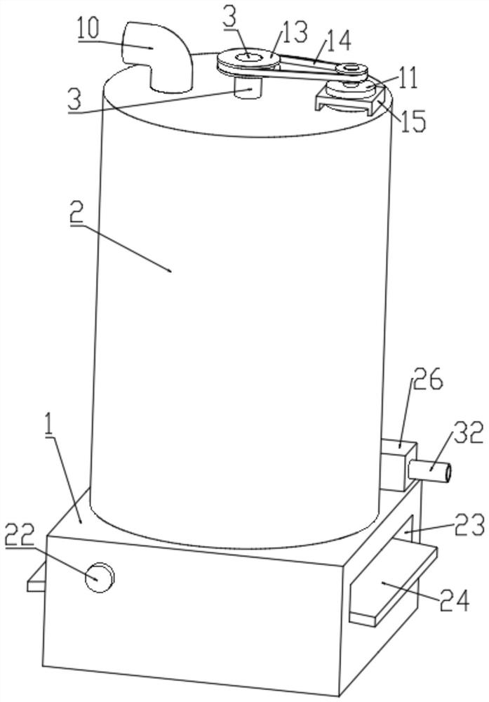
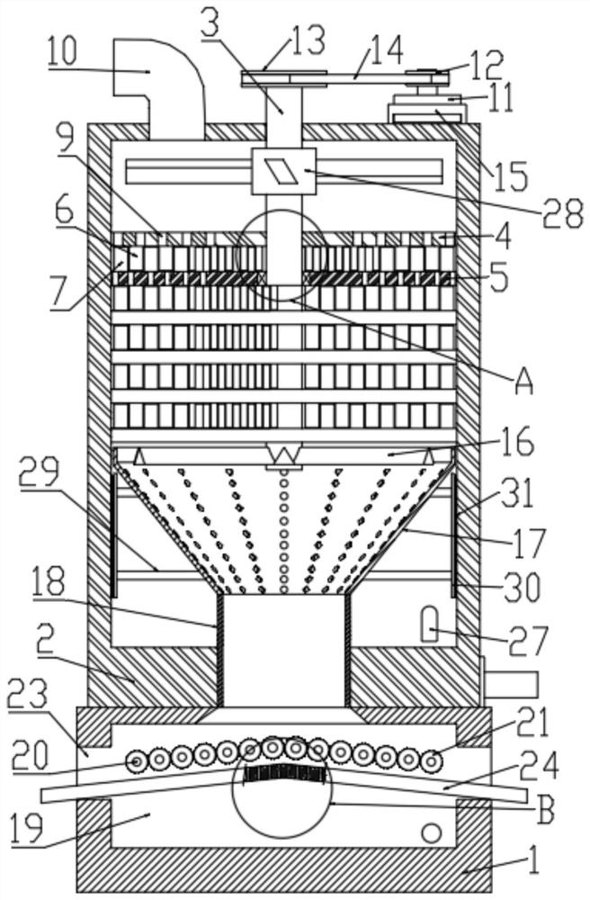
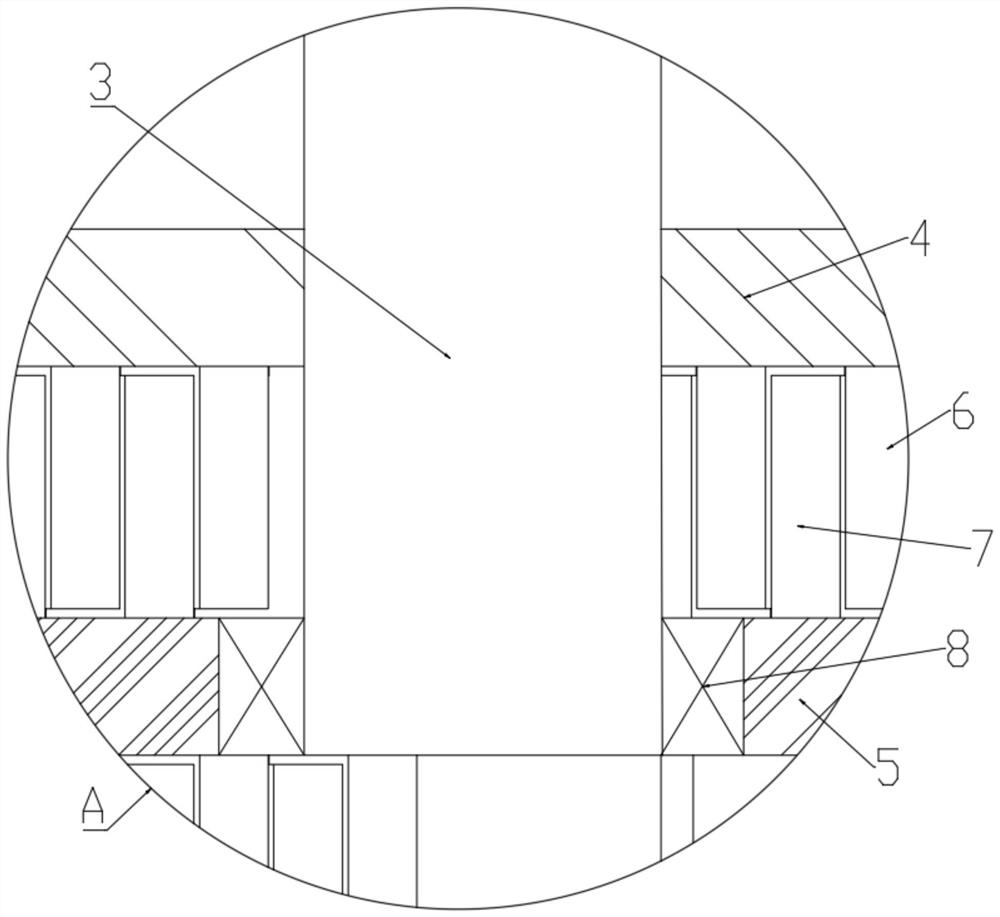
[0030] see Figure 1-6 , a high-quality and high-yield oil processing filter device, comprising a base 1, a cylinder 2 is fixedly installed on the upper surface of the base 1, a filter assembly is arranged in the cylinder 2, and the filter assembly includes a rotating shaft 3 and multiple groups of filter press components, filter press components Including a first filter plate 4, a second filter plate 5, a plurality of first pressure plates 6 and a plurality of second pressure plates 7, the rotating shaft 3 is vertically rotated and sleeved in the cylinder 2, and the first filter plate 4 is horizontally fixed and sleeved on the rotating shaft 3, the second filter plate 5 is horizontally fixed and sleeved in the cylinder body 2, and the middle part is rotatably connected with the rotating shaft 3 through the sealing bearing 8, and the plurality of first pressure plates 6 are vertically fixed and installed on the bottom surface of the first filter plate 4, an...

Example Embodiment

[0036] Embodiment 2: The difference based on Embodiment 1 is that a cavity 19 is opened in the base 1, and an extrusion part is arranged in the cavity 19. The extrusion part includes a plurality of rollers 20, a plurality of rolling wheels 21 and In the second motor 22, a plurality of rollers 20 are installed in the base 1 for horizontal and radial rotation, and a plurality of rolling wheels 21 are respectively fixed and sleeved on the plurality of rollers 20, and the two adjacent ones are in meshing contact, the second The motor 22 is horizontally and fixedly sleeved in the base 1 , and the output shaft is fixedly connected to the end of one of the rollers 20 through a coupling.

[0037] The left and right sides of the base 1 are provided with discharge ports 23 horizontally, and the two discharge ports 23 are connected to the cavity 19. A material guide plate 24 is horizontally arranged in the cavity 19. The material guide plate 24 is arched, and the front and rear two The e...

Example Embodiment

[0040] Embodiment 3: The difference based on Embodiment 1 is that two sets of cleaning parts are symmetrically arranged on the outside of the conical cylinder 17, and the cleaning parts include two connecting rods 29, scrapers 30 and a plurality of hairs 31, and two connecting rods 29 The squeegee 30 is fixed and installed horizontally on the side of the conical cylinder 17, the scraper 30 is vertically fixed and installed on one end of the two connecting rods 29 away from the conical cylinder 17, and the multiple hairs 31 are fixed horizontally and fixedly installed on the side of the scraper 30 away from the connecting rod 29, And one end away from the scraper 30 is in sliding contact with the inner wall of the cylinder 2 .

[0041] Under the centrifugal action, the oil is thrown out, and at the same time, the conical cylinder 17 drives the scraper 30 to rotate through the connecting rod 29, and the scraper 30 drives a plurality of filaments 31 to rotate, scraping off the oil...


PUM


Abstract

The invention discloses a filtering device for processing high-quality and high-yield oil plants, and belongs to the technical field of oil plant processing. A filtering device for processing high-quality and high-yield oil plants comprises a base, a barrel is fixedly mounted on the upper surface of the base, a filtering assembly is arranged in the barrel and comprises a rotating shaft and a plurality of filter pressing parts, and each filter pressing part comprises a first filter plate, a second filter plate, a plurality of first pressing plates and a plurality of second pressing plates. The rotating shaft is vertically and rotatably sleeved in the cylinder body, a plurality of filter holes are vertically formed in the first filter plate and the second filter plate, the apertures of the plurality of filter holes are sequentially reduced from top to bottom, a feeding pipe is vertically and fixedly sleeved at the top end of the cylinder body, a driving part is arranged at the top end of the cylinder body, and a centrifugal part is arranged at the bottom end of the rotating shaft; the oil processing device effectively solves the problems that a filtering mechanism in an existing oil processing device is simple, oil in residues is lost, the oil yield is affected, and meanwhile waste is caused.

Description

technical field [0001] The invention relates to the technical field of oil processing, in particular to a filtering device for high-quality and high-yield oil processing. Background technique [0002] Most of the edible oil in daily life is extracted from plants. With the development of life, people use more and more edible oil in life, and the merchants that produce edible oil are also constantly improving the oil yield of oil extraction. Most of them are extracted from plant particles by pressing. During the pressing process, the oil will be filtered many times to improve the oil yield. [0003] The filter mechanism in the existing oil processing device is relatively simple, and only has the function of filtering the residue in the oil, which cannot be further processed, resulting in the loss of the oil in the residue, affecting the oil yield, and causing waste. SUMMARY OF THE INVENTION [0004] 1. The technical problem to be solved by the present invention [0005] Th...

Claims


Application Information

Patent Timeline
IPC IPC(8): B01D36/00B01D33/15B01D33/27B01D33/42B01D33/46B01D33/64B01D33/72C11B3/00C11B13/00
CPCB01D36/00B01D33/15B01D33/27B01D33/42B01D33/64B01D33/72B01D33/466C11B3/008C11B13/00Y02W30/74
Inventor 郑黎静申森刘抒影胡晓冰王振强王振伟郑劭珊李耀辉曹博
Owner YELLOW RIVER CONSERVANCY TECHN INST
Why Eureka
Try Eureka