Method for internally arranging steel wire without exposure in manufacturing process of long and thin sand core

A production process and steel wire technology, applied in cores, manufacturing tools, casting molding equipment, etc., can solve problems affecting casting quality, steel wire exposure or offset, casting adhesion, etc., to reduce casting scrap rate, improve molding quality, Avoid the effect of excessive offset

Pending Publication Date: 2022-06-03
DONGFENG FORGING
0 Cites 0 Cited by

AI-Extracted Technical Summary

Problems solved by technology

[0005] In view of the above-mentioned technical defects and application requirements, the present invention proposes a method for built-in steel wires without exposure during the production process of slender sand cores, aiming at solving the problem of the existing methods of built-in steel wires in sand ...

Method used

Preferably, in described step 1, hanging needle 1 and steel wire 2 contact ends adopt tapered structure, the one, be convenient to the pressing of steel wire 2 and put in place, and press tighter more, the 2nd, can make hanging needle when ...

Abstract

The invention discloses a method for arranging a steel wire without exposure in the manufacturing process of a long and thin sand core. The method comprises the following steps: step 1, prefabricating three step-shaped hanging needles according to the actual core manufacturing requirement; and 2, the prefabricated hanging needles are sequentially installed in the core box cavity, the hanging needles have certain offset compared with the steel wires, and therefore the steel wires can be extruded more appropriately according to needs, and the positions of the steel wires are controlled. The method has the beneficial effects that the three hanging needles are arranged in the cavity in the static core box of the sand core in advance in an offset manner, so that a steel wire can be arranged in the center of the cavity of the core box in a suspended and limited manner, the steel wire can be completely wrapped after the sand core is formed, and the steel wire is located in the center of the formed sand core; the exposure of the steel wire after the sand core is formed and the excessive deviation of the steel wire relative to the center of the sand core after the sand core is formed are avoided, the forming quality of the sand core is greatly improved, and the rejection rate during casting machining is further reduced.

Application Domain

Technology Topic

Image

  • Method for internally arranging steel wire without exposure in manufacturing process of long and thin sand core
  • Method for internally arranging steel wire without exposure in manufacturing process of long and thin sand core
  • Method for internally arranging steel wire without exposure in manufacturing process of long and thin sand core

Examples

  • Experimental program(1)

Example Embodiment

[0023] A method for embedding steel wires without exposure during the production of elongated sand cores, comprising the steps of:
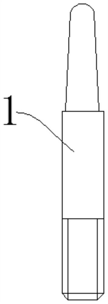
[0024] Step 1: Prefabricate three stepped hanging needles 1 according to the actual core making requirements;
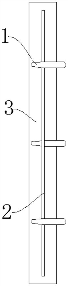
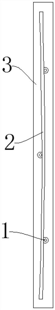
[0025] Step 2: Install the prefabricated hanging needles 1 in the core box cavity 3 in turn, and make the hanging needles 1 have a certain offset compared to the steel wire 2, so that the steel wire 2 can be squeezed more appropriately according to the needs, and the control Wire 2 position;
[0026] Step 3: The steel wire 2 that needs to be placed inside the sand core is in contact with the tapered end of the hanging needle 1 in turn, and the steel wire 2 is pre-pressed and fixed under its own elasticity by pressing;
[0027] Step 4: After the steel wire 2 is laid out, just inject the sand material for making the sand core into the core box cavity 3 and solidify it, and then the prefabrication of the sand core can be realized to ensure that the sand core can completely wrap the steel wire 2 inside. .
[0028] Preferably, the core forming part of the core box is composed of two parts: a static core box and a moving core box. During core making, the static core box is fixed, and the moving core box is moved to perform mold clamping and parting. The core box cavity 3 is formed by the static core box. The core box and the moving core box are formed after mold clamping, and the hanging needle 1 of the fixed steel wire 2 is installed in the static core box.
[0029] Preferably, in the step 1, the contact end of the hanging needle 1 and the steel wire 2 adopts a tapered structure. First, it is convenient for the steel wire 2 to be pressed into place, and the more you press it, the tighter it is, and the second is to facilitate the hanging needle 1. Pull out from the sand core; in the step 1, the connecting end of the hanging needle 1 and the core box cavity 3 adopts a threaded structure, which is convenient for the convenient installation of the hanging needle 1.
[0030] Preferably, in the step 3, the steel wire 2 is just located in the center of the core box cavity 3 after being fixed, and the position of the hanging needle 1 is reasonably offset so that the wire 2 can generate an appropriate amount of elastic force, and the tapered end of the hanging needle 1 and the steel wire are used. 2 elastic force, the steel wire 2 can be reliably placed in the middle of the core box cavity 3, and the purpose of the steel wire 2 being located in the middle of the sand core is achieved after the core is made. Of course, the sand core made in this way will have three small round holes. , but the small round holes are very easy to fill. It can be filled and repaired with repairing mud. The repairing mud repairing and filling the small holes is firm and will not fall off, which completely solves the problem of the exposed steel wire 2 in the sand core and the adhesion of the steel wire 2 to the casting during casting. .
[0031] The above embodiments are only used to illustrate the technical solutions of the present invention, but not to limit them; although the present invention has been described in detail with reference to the foregoing embodiments, those of ordinary skill in the art should understand that: The recorded technical solutions are modified, or some technical features thereof are equivalently replaced; and these modifications or replacements do not make the essence of the corresponding technical solutions deviate from the spirit and scope of the technical solutions of the embodiments of the present invention.

PUM

no PUM

Description & Claims & Application Information

We can also present the details of the Description, Claims and Application information to help users get a comprehensive understanding of the technical details of the patent, such as background art, summary of invention, brief description of drawings, description of embodiments, and other original content. On the other hand, users can also determine the specific scope of protection of the technology through the list of claims; as well as understand the changes in the life cycle of the technology with the presentation of the patent timeline. Login to view more.

Similar technology patents

Foundry molding sand processing and feeding device

InactiveCN104439050AImprove molding qualityRealization of continuous processing productionMould handling/dressing devicesEngineeringMolding sand
Owner:HEFEI RUIHONG HEAVY MACHINERY

Classification and recommendation of technical efficacy words

Why Eureka
Try Eureka