Micro-concave roller gap engraving process

A concave roll and gap technology, which is applied in the field of micro-concave roll gap engraving technology, can solve problems such as difficulty in meeting the design requirements of diaphragm coatings, and achieve the effect of broadening the scope of use, broadening the scope of application, and reducing difficulty.

Pending Publication Date: 2022-06-03
华鼎国联四川动力电池有限公司
View PDF0 Cites 0 Cited by
  • Summary
  • Abstract
  • Description
  • Claims
  • Application Information

AI Technical Summary

Problems solved by technology

[0005] The purpose of the present invention is to provide a gap engraving process for micro-concave rollers to solve the problem that the traditional anilox design of existing micro-concave rollers is difficult to meet the design requirements of more diaphragm coatings

Method used


Image

  • Micro-concave roller gap engraving process
  • Micro-concave roller gap engraving process
  • Micro-concave roller gap engraving process

Examples


Embodiment 1

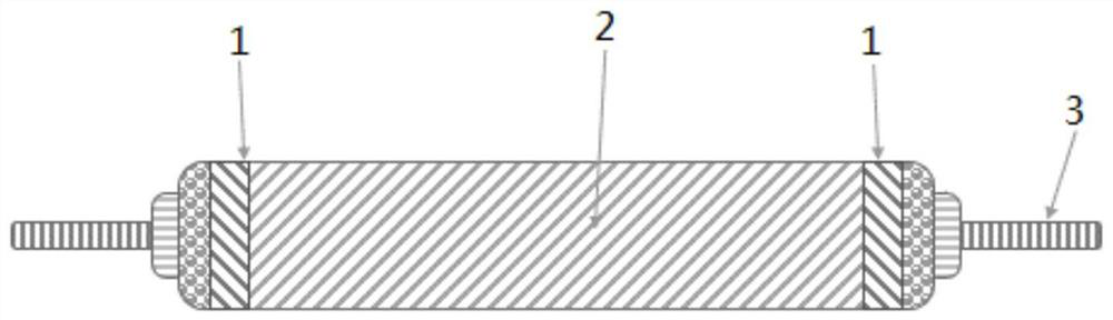
[0035] Please refer to figure 1 As shown, in the micro-gravure roller gap engraving process in this embodiment, the middle part of the roller surface of the micro-gravure roller is a blank area and does not need to be engraved, only the engraving area is engraved, and the engraving area is two strip-shaped areas. The pit depth of the engraving area is 80 μm, the line speed is designed to be 120 lines, the width of the coating area is 2 mm, and the spacing is 285 mm. Bottom-coated primer diaphragm, the width of this diaphragm is 289mm, and there are 2mm areas at both ends of the edge with ceramic coating, and the coating thickness is 4μm, this diaphragm can be applied to 322 size power cells.

Embodiment 2

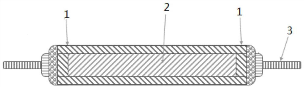
[0037] Please refer to figure 2 As shown, in the engraving process of the micro-gravure roller gap in this embodiment, the engraving area of ​​the roller surface of the micro-gravure roller is 4 strip-shaped areas, 2 vertical bearings, 2 parallel bearings, and the part other than the engraving area is a blank area. Sculpture. The pit depth of the engraving area is 100μm, the line speed is designed to be 160 lines, the width of the engraving area is 2mm, the spacing of the strip area of ​​the vertical bearing is 285mm, and the spacing of the strip area of ​​the parallel bearing is 93mm. Coating the ceramic slurry with a viscosity of 80mpa s at room temperature, the edge-coated diaphragm with only edge coating can be obtained directly after coating and slitting. With a coating thickness of 3μm, this diaphragm can be applied to 322 size power cells.

Embodiment 3

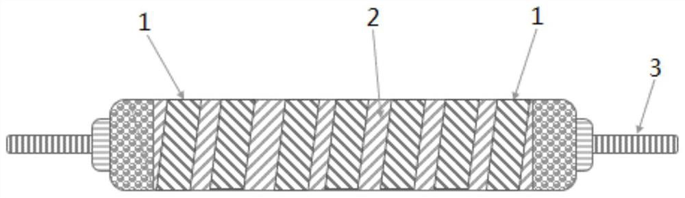
[0039] Please refer to image 3 As shown, in the micro-gravure roller gap engraving process of this embodiment, the engraving area of ​​the roller surface of the micro-gravure roller is several strip-shaped areas, and the part other than the engraving area is a blank area without engraving. The area ratio of the engraving area to the blank area should be less than 3:1, the strip engraving area and the bearing direction should be 60° to 80°, parallel to each other, the pit depth of the engraving area is 100 μm, and the line speed is designed to be 160 lines. Coating the ceramic slurry with a viscosity of 200mpa s at room temperature, the edge-coated diaphragm with only edge coating can be directly obtained after coating and slitting. With a coating thickness of 3μm, this diaphragm can be applied to 322 size power cells.


PUM

PropertyMeasurementUnit
Viscosityaaaaaaaaaa
Thicknessaaaaaaaaaa

Abstract

The invention discloses a micro-concave roller gap engraving process, and belongs to the technical field of production of lithium electronic diaphragms. The method comprises the following steps that the roller surface of the micro-concave roller is divided into a carving area and a blank area, and the carving area is carved; according to the invention, the conventional micro-concave roller reticulate pattern design is abandoned, and the reticulate pattern roller is designed according to the diaphragm to be coated in a clearance carving manner, so that the difficulty of special coating is solved in a targeted manner, the diaphragm coating is not limited by the reticulate pattern carved by the micro-concave roller in a full-width manner any more, and the coated diaphragm structure is more diversified.

Description

technical field [0001] The invention relates to the technical field of lithium electronic diaphragm production, in particular to a micro-gravure gap engraving process. Background technique [0002] The lithium-ion battery separator is one of the important components of the lithium-ion battery. Its function is to separate the materials of the positive electrode and the negative electrode, allowing ions to pass through without allowing electrons to pass through. Its performance determines the interface structure and internal resistance of the battery. It also directly affects the capacity, cycle and safety performance of the battery. [0003] In recent years, with the diversification of lithium-ion battery applications, the requirements for separators have become more and more diversified. Especially after 2018, special coating methods such as gap coating, spot coating, and edge coating have gradually appeared. However, such coating methods are limited by coating rollers. In...

Claims


Application Information

Patent Timeline
IPC IPC(8): B23K26/362
CPCB23K26/362B23K2101/36Y02E60/10
Inventor 倪靖
Owner 华鼎国联四川动力电池有限公司
Why Eureka
Try Eureka