Supercharge Your Innovation With Domain-Expert AI Agents!

Transmission tower for power transmission

A technology for power transmission and transmission towers, which is applied in the direction of towers, general water supply saving, cleaning methods using tools, etc. It can solve problems such as adhesion of moisture to transmission towers, increased load bearing of transmission towers, and problems affecting the safety of transmission towers, so as to increase convenience. , the effect of easy installation

Pending Publication Date: 2022-06-03
曾伯乐
View PDF0 Cites 0 Cited by
  • Summary
  • Abstract
  • Description
  • Claims
  • Application Information

AI Technical Summary

Problems solved by technology

[0003] 1. When the transmission tower is used outdoors, the surface of the transmission tower is easy to absorb birds to rest, and a bird's nest may be built on the transmission tower, which makes the surface of the transmission tower easy to wear, thus affecting the transmission of electricity;
[0004] 2. When the weather is cold, cooperate with repelling birds, resulting in water sticking to the surface of the transmission tower, which is easy to cause the surface of the transmission tower to freeze, which will increase the load bearing of the transmission tower and affect the safety of the transmission tower

Method used


Image

  • Transmission tower for power transmission
  • Transmission tower for power transmission
  • Transmission tower for power transmission

Examples


Embodiment 1

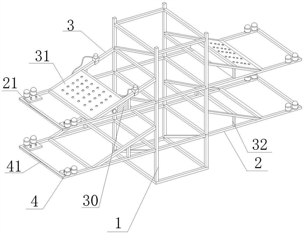
[0032] like Figure 1-7 As shown, the present invention provides a transmission tower for power transmission, including a transmission tower 1, a support frame 2, a mounting frame 3 and a lap joint 4, and a support frame 2 is fixedly installed on both sides of the top of the power transmission tower 1, which supports A mounting frame 3 is fixedly installed on the top of the frame 2, a reinforcing column 32 is fixedly installed on the side of the mounting frame 3, and a lap 4 is fixedly installed at one end of the installation frame 3 away from the transmission tower 1, and one end of the installation frame 3 is close to the lap 4. The pressure sensor 21 is arranged on the surface of the mounting frame 3, the signal board 41 is fixedly installed on the inner side of the installation frame 3, the water storage tank 31 is arranged on the inner side of the installation frame 3, and the top of the water storage tank 31 is provided with a collection hole 311, and the inside of the co...

Embodiment 2

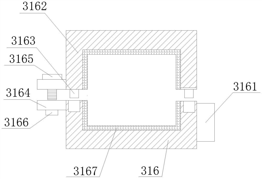
[0035] like Figure 1-7As shown, on the basis of Embodiment 1, the present invention provides a technical solution: preferably, connecting blocks 3161 are fixedly connected on both sides of the water storage tank 31, and a mounting block 316 is fixedly installed on the other side of the connecting block 3161, The inner side of the mounting block 316 is fixedly installed with a buffer pad 3167, the inner side of the buffer pad 3167 is fixedly mounted on the outer side of the support frame 2, the top of the two sides of the mounting block 316 is provided with a clamping groove, and the inner side of the clamping groove is provided with a clamping column 3163, A limit block 3162 is fixedly installed on the top of the clamping column 3163, a socket block 3164 is fixedly installed on one side of the limit block 3162 and the installation block 316, and the inner thread of the socket block 3164 is connected with a fixing bolt 3165, and the bottom thread of the fixing bolt 3165 A thre...

Embodiment 3

[0038] like Figure 1-7 As shown, on the basis of Embodiment 1, the present invention provides a technical solution: preferably, the bottom of the sprinkler 37 is fixedly connected with the conveying base 36, the surface of the conveying base 36 is provided with a connecting hole 371, and the interior of the connecting hole 371 It is fixedly connected to one end of the connecting hose, the bottom of the conveying base 36 is fixedly installed with a moving slider 35, the inner side of the moving slider 35 is provided with a scraper pad 341, the top of the scraper pad 341 is provided with a sponge pad 3413, and the top of the sponge pad 3413 A friction pad 3411 is fixedly installed, a friction column 3412 is arranged on the surface of the friction pad 3411, a drive chute 33 is opened on the outer side of the mounting frame 3, and a transmission block 34 is movably installed inside the drive chute 33, and the outer side of the transmission block 34 is fixedly installed On both si...


PUM


Abstract

The invention discloses a transmission tower for electric power transmission, and relates to the technical field of electric power transmission, the transmission tower comprises a power transmission tower frame, supporting frames, mounting frames and lap joint devices, the supporting frames are fixedly mounted on the two sides of the top of the power transmission tower frame, the mounting frames are fixedly mounted on the tops of the supporting frames, and reinforcing columns are fixedly mounted on the side faces of the mounting frames; a lap joint device is fixedly mounted at the end, away from the power transmission tower, of the mounting frame. A pressure sensor is used for sensing, then a conveying water pump is matched for providing power to drive internal water to be conveyed into a conveying base, then a sprayer is matched for spraying water, and then a driving sliding groove and a transmission block are matched with each other to drive the sprayer to move, so that the movable spraying function is achieved; the problems that the surface of the power transmission tower is prone to absorbing birds for rest, a bird nest may be built on the power transmission tower, and the surface of the power transmission tower is prone to abrasion are solved, the device can conveniently drive the birds, and the convenience of the device is improved.

Description

technical field [0001] The present invention relates to the technical field of electric power transmission, in particular to a transmission tower for electric power transmission. Background technique [0002] The transmission tower is the support point of the overhead line. If one circuit is erected on the transmission tower, it is a single-circuit transmission tower, and if two circuits are erected on the transmission tower, it is a double-circuit transmission tower. Single loop refers to a loop with one power supply for a load; double loop refers to a loop with two power supplies for a load. Generally, enterprises with high requirements on power supply reliability, or important substations in the region, use double-circuit power supply, which can protect one of the power sources from power failure, and the other power source can continue to supply power. However, the general requirements for power supply reliability are not High and medium-sized users often use a single p...

Claims


Application Information

Patent Timeline
Patent Type & Authority Applications(China)
IPC IPC(8): E04H12/00E04H12/24E03B3/02B01D35/027B01D29/64B08B1/00A01M29/06
CPCE04H12/00E04H12/24E03B3/02B01D35/0276B01D29/6423A01M29/06B08B1/143B08B1/30Y02A20/108
Inventor 曾伯乐
Owner 曾伯乐
Features
  • R&D
  • Intellectual Property
  • Life Sciences
  • Materials
  • Tech Scout
  • Unparalleled Data Quality
  • Higher Quality Content
  • 60% Fewer Hallucinations
Learn More