A method for in-situ deep in-situ supercritical storage of flue gas

A flue gas and supercritical technology, which is applied in earth drilling, climate sustainability, and other gas emission reduction technologies, can solve problems such as high costs, slow process steps, and huge equipment investment costs, and achieve storage capacity Large, diffuse, rich storage capacity effect

Active Publication Date: 2022-07-29
TAIYUAN UNIV OF TECH
View PDF5 Cites 0 Cited by
  • Summary
  • Abstract
  • Description
  • Claims
  • Application Information

AI Technical Summary

Problems solved by technology

On the other hand, the cost of technical equipment investment and transformation around carbon purification, compression and transportation is also huge
Therefore, the high cost and complicated process links slow down the large-scale commercialization of CCUS technology

Method used


Image

  • A method for in-situ deep in-situ supercritical storage of flue gas
  • A method for in-situ deep in-situ supercritical storage of flue gas
  • A method for in-situ deep in-situ supercritical storage of flue gas

Examples


Embodiment 1

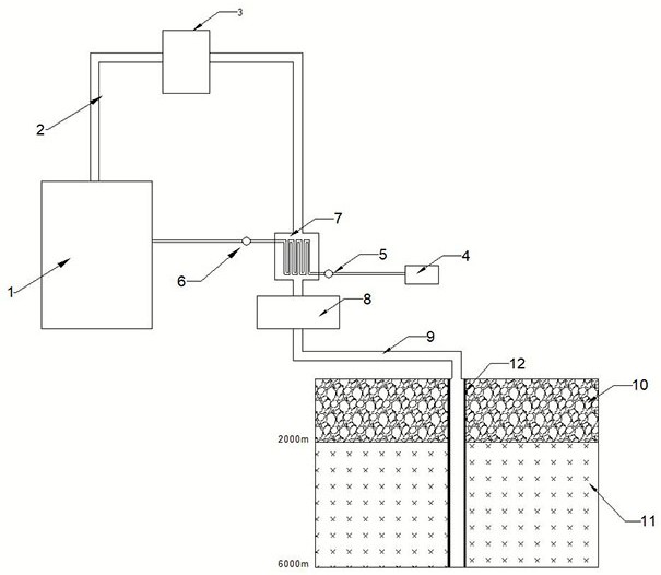
[0041] A method for in-situ and deep supercritical storage of power plant flue gas, such as figure 1 , 2 , 3 and 6, the specific steps are as follows:

[0042] 1) Under the condition that the normal power generation of the power plant and the safety and stability of the power facilities are not affected, deep drilling is carried out in a certain range of open space in the power plant area 1. The drilling depth exceeds 2000m, and the target well depth reaches 5000m-7000m. Casing 12 is installed in the hole and cemented.

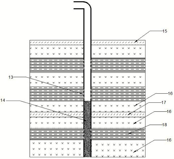
[0043] 2) Sampling the cores of different formations over 2000m in the drilling, and experimentally measure the porosity, permeability, water content, gas adsorption / desorption rate and mechanical strength parameters of rocks in different formations, and combine the relevant geological and hydrological conditions with the formation. Conditions (thickness, dip, water content, and fault characteristics), through comprehensive evaluation, analysis and screening...

Embodiment 2

[0050] A method for in-situ and deep supercritical storage of power plant flue gas, such as figure 1 , 2 , 4 and 6, the specific steps are as follows:

[0051] 1) Under the condition that the normal power generation of the power plant and the safety and stability of the power facilities are not affected, deep drilling is carried out in a certain range of open space in the power plant area 1. The drilling depth exceeds 2000m, and the target well depth reaches 5000m-7000m. Casing 12 is installed in the hole and cemented.

[0052] 2) Sampling the cores of different formations over 2000m in the drilling, and experimentally measure the porosity, permeability, water content, gas adsorption / desorption rate and mechanical strength parameters of rocks in different formations, and combine the relevant geological and hydrological conditions with the formation. Conditions (thickness, dip, water content, and fault characteristics), through comprehensive evaluation, analysis and screening...

Embodiment 3

[0060] A method for in-situ and deep supercritical storage of power plant flue gas, such as figure 1 , 2 , 5 and 6, the specific steps are as follows:

[0061] 1) Under the condition that the normal power generation of the power plant and the safety and stability of the power facilities are not affected, deep drilling is carried out in a certain range of open space in the power plant area 1. The drilling depth exceeds 2000m, and the target well depth reaches 5000m-7000m. Casing 12 is installed in the hole and cemented.

[0062] 2) Sampling the cores of different formations over 2000m in the drilling, and experimentally measure the porosity, permeability, water content, gas adsorption / desorption rate and mechanical strength parameters of rocks in different formations, and combine the relevant geological and hydrological conditions with the formation. Conditions (thickness, dip, water content, and fault characteristics), through comprehensive evaluation, analysis and screening...


PUM


Abstract

The invention belongs to the technical field of carbon dioxide geological sequestration, and relates to a method for in-situ deep supercritical sequestration of flue gas; drilling is performed in an area within 10 km from the surface of a flue gas discharge port; The storage layer in the ground is sealed; the depth of the storage layer from the surface is more than 2000 meters; the storage layer is the key rock layer inside the deep ground; the invention makes the flue gas in a supercritical state stably and nearby sealed at a depth of 2000 m below the ground , to achieve the purpose of long-term, safe and effective storage effect; this method adopts the "in-situ deep" injection method of flue gas near the power plant, and does not require CO 2 The "capture-purification-transport" process and related technical equipment investment simplifies the injection process and greatly saves operating costs.

Description

technical field [0001] The invention belongs to the technical field of carbon dioxide geological storage, and relates to a method for in-situ deep supercritical storage of flue gas. Background technique [0002] Fossil fuels will continue to be the dominant consumable for heat generation and power generation in the current period and for a long time to come. However, in the process of using fossil fuels to generate heat, the air pollution and greenhouse effect caused by them are also key issues that we cannot ignore. An effective solution to global warming and the greenhouse effect is to reduce CO 2 emissions or to CO 2 to archive. Carbon capture, utilization and storage (CCUS) has become a research hotspot. CCUS technology generally includes four basic processes: ① capture process; ② purification and compression process; ③ transportation process; ④ geological storage process. [0003] Research shows that the global CO 2 Among the emissions, the power plant is the larg...

Claims


Application Information

Patent Timeline
Patent Type & Authority Patents(China)
IPC IPC(8): E21B43/16
CPCE21B43/168E21B43/164Y02P90/70
Inventor 康志勤王磊赵阳升杨栋张宇星赵静吕兆兴
Owner TAIYUAN UNIV OF TECH
Why Eureka
Try Eureka