Sealing and fixing device for power plug cord of submersible motor for well

A technology for power plugs and submersible motors, which can be used in cable entry sealing devices, cable installation, motor generator connectors, etc. It can solve problems that affect sealing and safety, complex wiring and positioning processes, and affect production efficiency. , to prevent wrong insertion direction, improve production efficiency and product quality, and prevent wiring errors

Pending Publication Date: 2022-06-03
GUANGDONG RUIRONG PUMP IND
View PDF0 Cites 0 Cited by
  • Summary
  • Abstract
  • Description
  • Claims
  • Application Information

AI Technical Summary

Problems solved by technology

In the prior art, the sealing and fixing device for the power plug line of the submersible motor for well mainly includes a power socket that is sealed and fixed at the outlet of the power line of the upper head of the submersible motor for well and connected with the motor drive lead-out line and connected with the power cable flat. The power plug of the cable, and the pressure sealing plate that fixes the power plug on the upper head. The power socket includes an insulating plastic seat, which is consistent with the height of 3 to 4 protrusions arranged side by side and packaged on the plastic seat. The conductor ferrule pin, the tail of the conductor ferrule pin is connected to the motor drive lead wire, the power plug includes an insulating rubber plug and 3 to 4 conductor jack pins of the same height arranged in parallel and packaged in the insulating rubber plug, the The tail of the conductor jack pin is connected to the flat wire of the power cable. It also includes a protective sleeve embedded in the tail of the insulating rubber plug. The inside of the protective sleeve is filled with insulating sealant. When the power plug is pressed into the power socket, all the conductor pins should be inserted into the conductor jack pins, and the pressing plate is set outside the protective sleeve of the power plug, and the end of the protective sleeve is pressed by screws. The insulating rubber plug is fixed on the upper head. For the power plug and socket connected to the flat power cable and the power outlet of the upper head, their shape is usually round or oblong. The round shape should be inserted into the conductor. The core pins and conductor jack pins are arranged in an isosceles triangle. The wiring and positioning process is more complicated during production, which affects production efficiency. The oblong ones arrange the conductor core pins and conductor jack pins at linear intervals. The wiring and positioning process is relatively simple, and the installation is convenient
When installing, usually press the power socket connected to the motor drive lead-out line from the top into the position of the power line outlet of the upper head of the submersible motor for well use, and then cover the pressing plate outside the protective sleeve of the power plug, and insert the power plug The power socket and the end of the protective cover are pressed against the insulating rubber plug by screws and fixed on the upper head, so that the insulating rubber plug and the insulating plastic seat are compressed and expanded to seal, and the installation is more convenient. However, if this structure is installed When the board is not tight enough, the seal will be improper and cause water leakage. At the same time, when plugging and unplugging the power plug, it is easy to pull out the power socket at the same time, and it is easy to cause water leakage into the motor or cable, causing safety accidents and seriously affecting the sealing and safety.

Method used


Image

  • Sealing and fixing device for power plug cord of submersible motor for well
  • Sealing and fixing device for power plug cord of submersible motor for well
  • Sealing and fixing device for power plug cord of submersible motor for well

Examples


Embodiment Construction

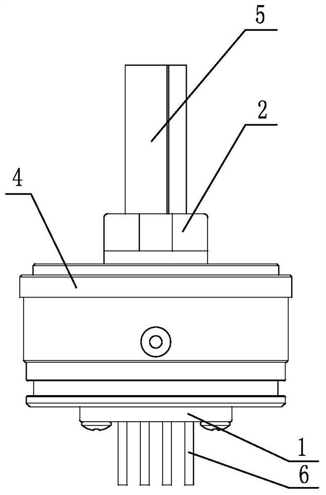
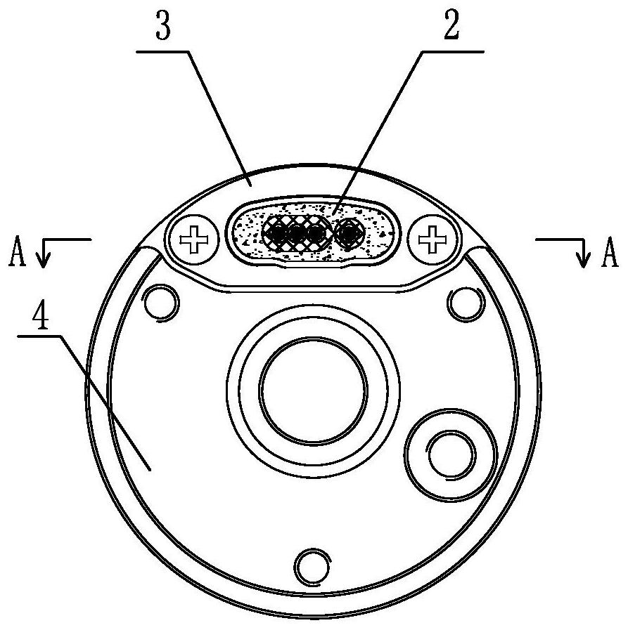
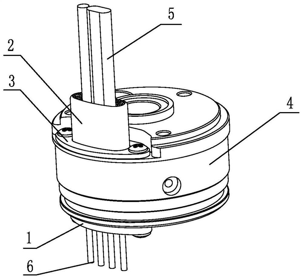
[0053] Depend on Figures 1 to 37 As shown, the embodiment of the sealing and fixing device for the power plug wire of the submersible motor for a well according to the present invention is: The power cord outlet 41 is connected in parallel with the power socket 1 of the motor drive lead wire 6 and the power plug 2 connected with the power cable flat wire 5, and the power plug 2 is fixed on the upper head 4. The sealing plate 3, Depend on Figures 4 to 9 As shown in 27-32, the power socket 1 includes an insulating plastic seat 11, and 3-4 conductor ferrule pins 12 with the same protruding height, which are arranged and packaged on the plastic seat side by side. The tail of 12 is connected to the motor drive lead wire 6, which is connected by Figures 4 to 5 As shown in 10 to 16, the power plug 2 includes an insulating rubber plug 21 and 3 to 4 conductor jack pins 22 of the same height that are arranged in parallel and packaged in the insulating rubber plug. The tail of the c...


PUM


Abstract

The invention discloses a sealing and fixing device for a power plug cord of a submersible motor for a well, which comprises a power socket which is tightly fixed at a power cord outlet and is connected with a motor driving outgoing line, a power plug which is connected with a power cable flat wire, and a pressing and sealing plate for fixing the power plug, the power plug comprises an insulating rubber plug, 3-4 conductor jack needles and a protective sleeve which is internally filled with insulating sealant to package the conductor jack needles and the end part of the power cable flat wire together, the press sealing plate is sleeved at the outer end part of the protective sleeve to press and fix the insulating rubber plug, the insulating plastic seat is arc-shaped, and the waist part of the insulating plastic seat is provided with a sealing groove and a rubber sealing ring. A fixing lug is arranged at the tail part of the insulating plastic seat, the power line outlet is an arc-shaped long hole matched with the insulating plastic seat, the insulating rubber plug is arc-shaped, a sealing convex ring is arranged at the waist part of the insulating rubber plug, and the rubber sealing ring and the sealing convex ring are elastically sealed in the power line outlet; the sealing structure has the advantages of being good in sealing performance and not prone to disengagement.

Description

technical field [0001] The invention relates to a sealing and fixing device for a power plug wire of a submersible motor used in a well. Background technique [0002] The sealing and fixing device of the power plug wire of the submersible motor for wells is to facilitate the production process of the submersible motor without carrying cables to avoid affecting the production efficiency, and also to facilitate the transportation and installation and use of the user. It is a relatively popular wiring method at present. The sealing requirements for the sealing and fixing device of the power plug wire of the submersible motor for the well are very high. At the same time, in order to reduce the impact on the installation diameter of the submersible electric pump for the well, the flat wire of the power cable is often used, so the sealed power plug socket of the flat wire of the power cable is connected. It is the most needed technical solution for submersible motors for wells. I...

Claims


Application Information

Patent Timeline
Patent Type & Authority Applications(China)
IPC IPC(8): H02G15/013H02G15/04H01R4/00
CPCH02G15/013H02G15/046H01R4/00H01R2201/10Y02A30/14
Inventor 林德照陈国荣唐卫民
Owner GUANGDONG RUIRONG PUMP IND
Why Eureka
Try Eureka