
Continuous stamping device for metal processing

A punching device and metal processing technology, applied in metal processing equipment, feeding device, positioning device, etc., can solve the problems of punching hole position deviation, reduce processing efficiency, perforated plate movement, etc., and achieve accurate punching position and size , Improve punching quality and extend the effect of stroke range

Pending Publication Date: 2022-06-07
SHAOXING UNIV YUANPEI COLLEGE
View PDF0 Cites 2 Cited by
  • Summary
  • Abstract
  • Description
  • Claims
  • Application Information

AI Technical Summary

Problems solved by technology

[0003] Nowadays, the punching processing device of the perforated plate is easy to move during the punching operation, resulting in deviation of the punching hole position of the perforated plate, resulting in deformation of the non-stamping area, and the stamping and conveying of the perforated plate is mostly manual. For conveying, manual conveying has the defect of low efficiency, which leads to poor stamping effect, cannot carry out stamping operations continuously, and reduces processing efficiency, and manual conveying cannot accurately control the conveying distance, which will make the punching position of the perforated plate inconsistent. Processing requirements; for this reason, the present invention provides a kind of metal processing continuous stamping device

Method used


Image

  • Continuous stamping device for metal processing
  • Continuous stamping device for metal processing
  • Continuous stamping device for metal processing

Examples


Embodiment Construction

[0031] The embodiments of the present invention are described in detail below with reference to the accompanying drawings, but the present invention can be implemented in many different ways as defined and covered by the claims.

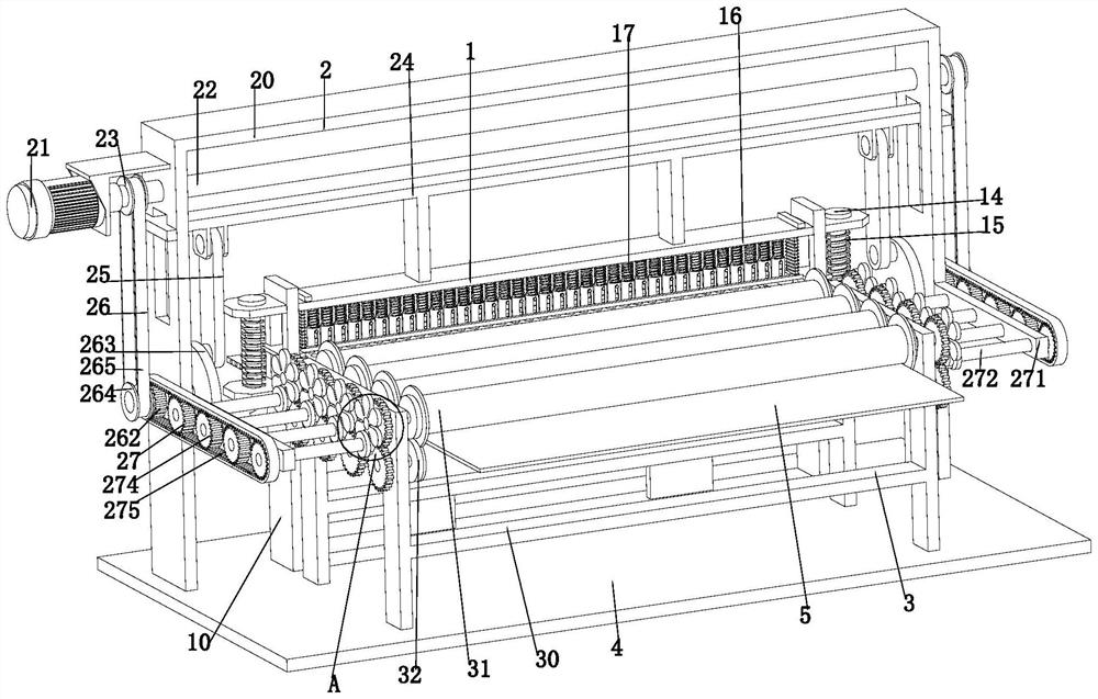
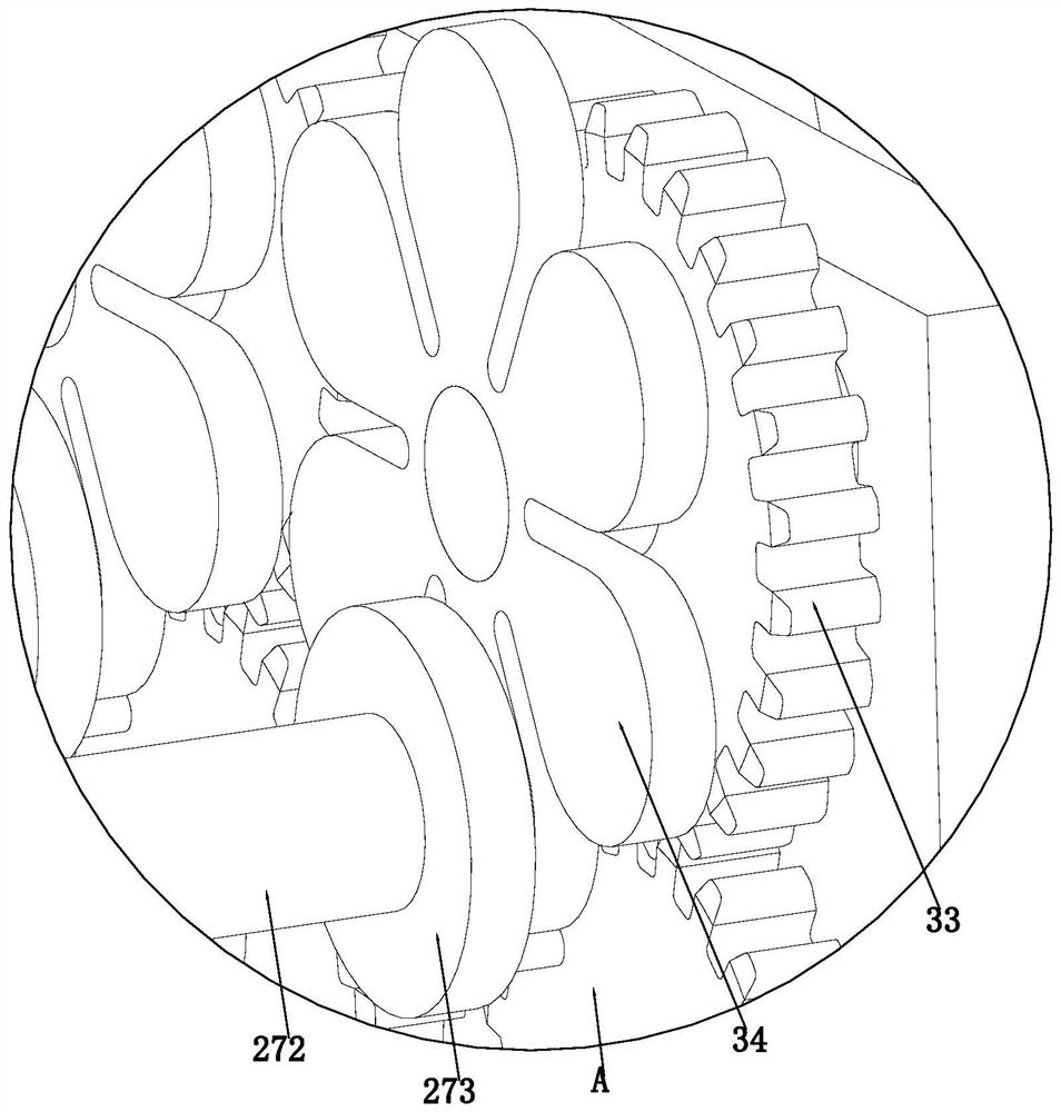
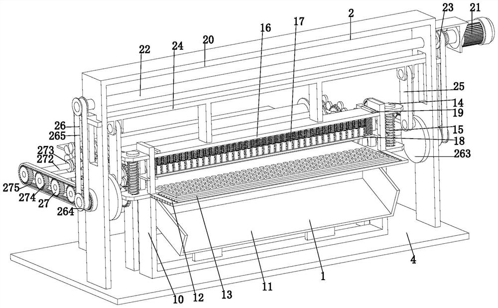
[0032] like Figure 1 to Figure 11 As shown, a metal processing continuous stamping device includes a pressing and cutting mechanism 1, a linkage mechanism 2, a progressive mechanism 3 and a base plate 4. The end surface of the base plate 4 is provided with a progressive mechanism 3, and the progressive mechanism 3 is directly behind. A pressing and cutting mechanism 1 is provided. Both the pressing and cutting mechanism 1 and the linkage mechanism 2 are installed on the end surface of the base plate 4 , and the pressing and cutting mechanism 1 is located below the linkage mechanism 2 .

[0033] see figure 1 , image 3 , Image 6 and Figure 8 , the pressing and cutting mechanism 1 includes a pressing and cutting support 10, a discharging guide f...


PUM


Abstract

The invention relates to the technical field of metal processing, in particular to a continuous stamping device for metal processing, which comprises a pressing and cutting mechanism, a linkage mechanism, a grading mechanism and a base plate, and solves the following problems of an existing stamping processing device for a perforated plate: the perforated plate is easy to move during punching operation; due to the fact that punching holes of the perforated plate are deviated, a non-punching area is deformed, the quality problem of the perforated plate is caused, punching conveying of the perforated plate mostly depends on manual conveying, manual conveying has the defect of low efficiency, the punching effect is poor, continuous punching operation cannot be conducted, and the production efficiency is high. And in addition, the conveying distance cannot be accurately controlled through manual conveying, so that the punching position of the perforated plate does not meet the machining requirement.

Description

technical field [0001] The invention relates to the technical field of metal processing, in particular to a continuous stamping device for metal processing. Background technique [0002] Metalworking, referred to as metalworking, is a process technology that processes metal materials into items, parts and components. Perforated metal plate is a common metal plate. Perforated metal plate is also known as perforated plate, perforated plate and perforated screen. The material of perforated plate is mostly stainless steel plate, aluminum plate, iron plate, copper plate, etc. Most of them are perforated aluminum plates, and perforated aluminum plates are light in material, good in chemical stability, beautiful in appearance, strong in three-dimensional effect, good in decoration and easy in assembly. They are widely used in architecture, landscape and indoor and outdoor decoration. The holes of perforated plates need to use punching devices. Stamping is performed. [0003] Duri...

Claims


Application Information

Patent Timeline
IPC IPC(8): B21D28/26B21D28/04B21D43/09B21D55/00
CPCB21D28/26B21D28/04B21D43/09B21D55/00Y02P70/10
Inventor 潘慧
Owner SHAOXING UNIV YUANPEI COLLEGE
Learn More