Synchronous displacement construction method for power transmission angle steel tower

A construction method and technology of synchronous displacement, applied in towers, wind power generation, construction, etc., can solve the problems that mobile cranes cannot pass, cannot realize the overall hoisting of iron towers, and the workload of disassembly and assembly is large, so as to reduce the time for high-altitude work and ensure The effect of stabilization and reduction of work intensity

Pending Publication Date: 2022-06-07
QINGHAI POWER TRANSMISSION & TRANSFORMATION ENG +2
View PDF0 Cites 0 Cited by
  • Summary
  • Abstract
  • Description
  • Claims
  • Application Information

AI Technical Summary

Problems solved by technology

[0002] With the continuous development of the power grid, the transformation of transmission lines in service is very common. Due to the constraints of line passages, terrain and other factors, some towers in the line reconstruction section are very close to the original line. In order to achieve "carbon peak, carbon neutral" resources Reuse, use the original line tower to realize the laying of the new line. Due to the terrain, the mobile crane cannot pass through, and the overall hoisting of the original iron tower cannot be realized. The traditional method of first dismantling and then reassembling can only be used, that is, the original line iron tower is removed from the top first. Dismantled one by one, transported to the new tower foundation and assembled manually one by one again, but because there are thousands of galvanized angle steels of different specifications, tens of thousands of bolts of different specifications, anti-loosening buckles, and bolts on the transmission angle steel tower. The anti-theft cap requires a lot of work to disassemble and assemble. In addition, the iron tower of the transmission line is exposed to the outside all the year round, so there are inevitably corrosion and other phenomena. The bolt disassembly process will inevitably cause damage to the thread, which will seriously affect the reassembly.

Method used


Image

  • Synchronous displacement construction method for power transmission angle steel tower
  • Synchronous displacement construction method for power transmission angle steel tower
  • Synchronous displacement construction method for power transmission angle steel tower

Examples


Embodiment Construction

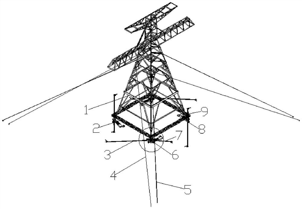
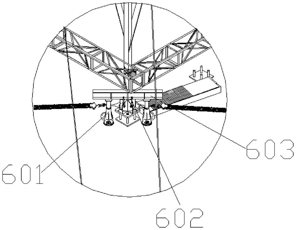
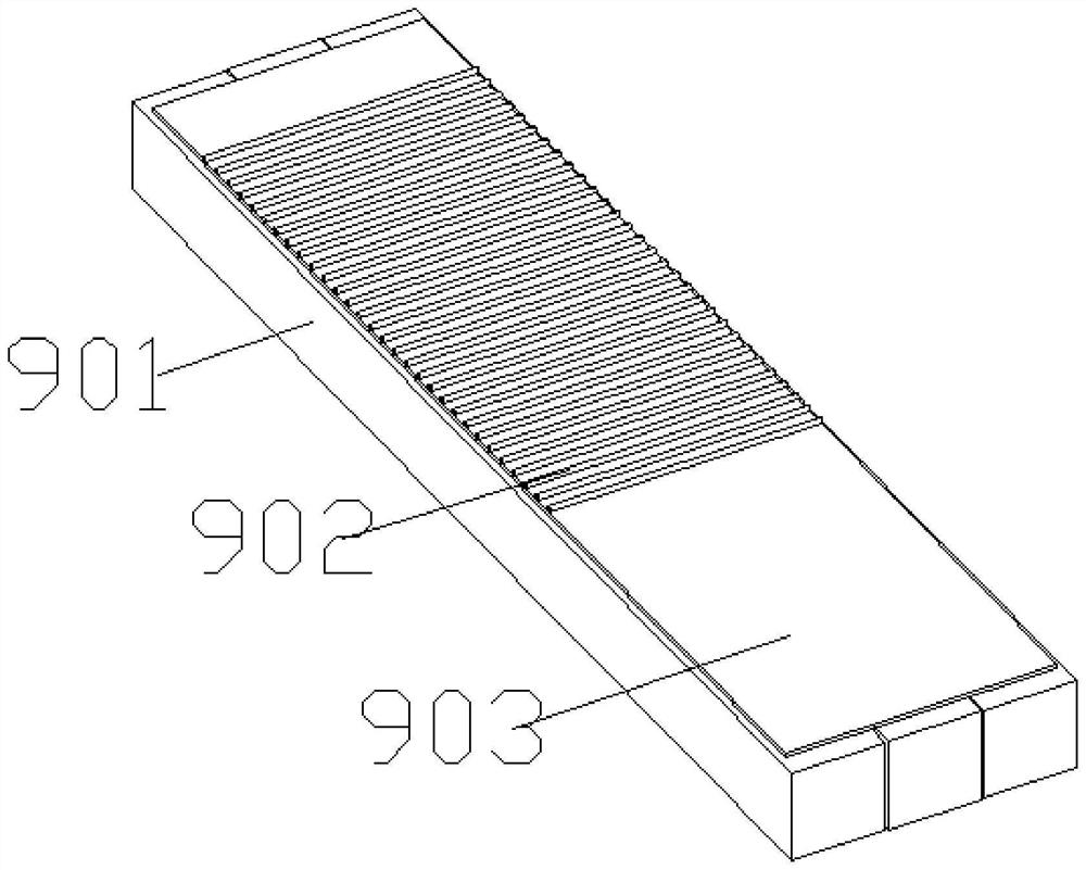
[0034] Attached below Figure 1-3 , clearly and completely describe the technical solutions in the embodiments of the present invention. Obviously, the described embodiments are only a part of the embodiments of the present invention, rather than all the embodiments. Based on the embodiments of the present invention, all other embodiments obtained by those of ordinary skill in the art without creative efforts shall fall within the protection scope of the present invention.

[0035] In the description of the present invention, it should be understood that the terms "portrait", "horizontal", "upper", "lower", "front", "rear", "left", "right", "vertical", The orientation or positional relationship indicated by "horizontal", "top", "bottom", "inner", "outer", etc. is based on the orientation or positional relationship shown in the drawings, and is only for the convenience of describing the present invention, rather than indicating or It is implied that the device or element refer...


PUM


Abstract

The invention discloses a synchronous displacement construction method for a power transmission angle steel tower. The synchronous displacement construction method comprises the following steps that S1, a connecting beam and a new base are poured; s2, tower legs of the angle steel tower are integrally fixed, and an angle steel tower body is reinforced; s3, a stay wire system, a jacking system, a traction system, a braking system and a sliding system are installed; and S4, the angle steel tower is moved and fixed to the new base, and movement of the angle steel tower is completed. According to the method, the processes of dismantling and assembling the power transmission angle steel tower can be omitted, the working intensity of workers is reduced, the high-altitude operation time is shortened, the personal safety of the workers is guaranteed, the construction efficiency is improved, and the purpose of recycling resources is achieved.

Description

technical field [0001] The invention belongs to the technical field of steel tower movement, and particularly relates to a synchronous displacement construction method for a power transmission angle steel tower. Background technique [0002] With the continuous development of the power grid, the transformation of service transmission lines is extremely common. Due to the constraints of line access, terrain and other factors, some towers in the transformation section of the line are very close to the original line. In order to achieve "carbon peaking and carbon neutrality" resources Reuse, use the original line tower to realize the laying of the new line. Due to the terrain, the mobile crane cannot pass through, and the overall hoisting of the original tower cannot be realized. Only the traditional method of first dismantling and then grouping can be used, that is, the original line tower is removed from the top. They were dismantled piece by piece, transported to the new tow...

Claims


Application Information

Patent Timeline
Patent Type & Authority Applications(China)
IPC IPC(8): E04G23/06E04H12/08E04H12/22
CPCE04G23/06E04H12/08E04H12/22Y02E10/72
Inventor 王春林靳义奎韩学文吕博张君祁永成王永俊白海龙邓杰荧张小龙牛泽楠李涓王庭张聪利程志军李相军李庆
Owner QINGHAI POWER TRANSMISSION & TRANSFORMATION ENG
Why Eureka
Try Eureka