Cutting fluid separation equipment for numerical control machine tool

A technology of separation equipment and CNC machine tools, applied in metal processing equipment, centrifuges, metal processing machinery parts, etc., can solve the problems of different shapes and sizes of metal chips, shortening the service life of cutting fluid, and reducing the anti-rust performance of cutting fluid, etc. Achieving good economic benefits, strengthening the percussion effect, and prolonging the service life

Pending Publication Date: 2022-06-17
方卫国
View PDF0 Cites 0 Cited by
  • Summary
  • Abstract
  • Description
  • Claims
  • Application Information

AI Technical Summary

Problems solved by technology

[0003] If the cutting fluid contains impurities, it will seriously affect the machining of the tool and damage the production equipment. The metal impurities in the cutting fluid will remain in the cutting fluid tank for a long time, and will react with the cutting fluid, resulting in the deterioration of the cutting fluid. Reduce the anti-rust performance of the cutting fluid and shorten the service life of the cutting fluid. In the industrial production process, the cutting fluid will be processed by the cutting fluid separation device, but the shape and size of the metal chips in the cutting fluid are different, which will lead to In the case of clogging, resulting in low efficiency, we propose a CNC machine tool cutting fluid separation equipment to solve the above problems

Method used


Image

  • Cutting fluid separation equipment for numerical control machine tool
  • Cutting fluid separation equipment for numerical control machine tool
  • Cutting fluid separation equipment for numerical control machine tool

Examples


Embodiment Construction

[0033] The technical solutions in the embodiments of the present invention will be clearly and completely described below with reference to the accompanying drawings in the embodiments of the present invention. Obviously, the described embodiments are only a part of the embodiments of the present invention, rather than all the embodiments. Based on the embodiments of the present invention, all other embodiments obtained by those of ordinary skill in the art without creative efforts shall fall within the protection scope of the present invention.

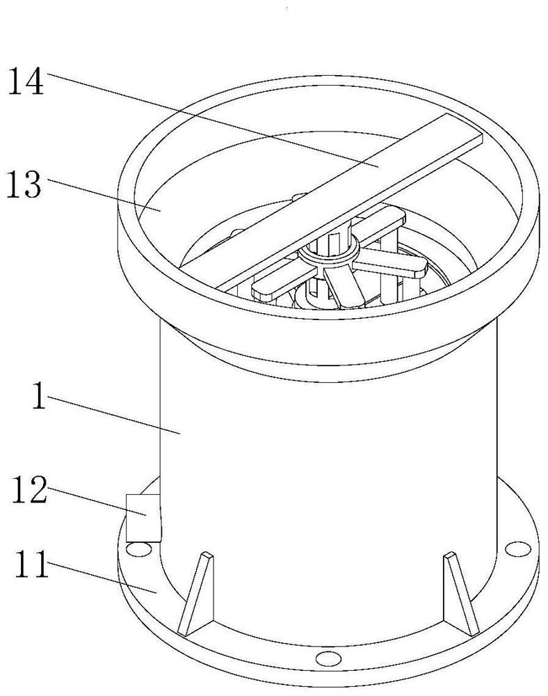
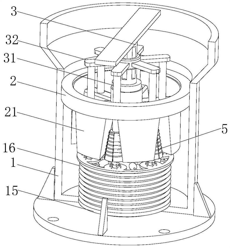
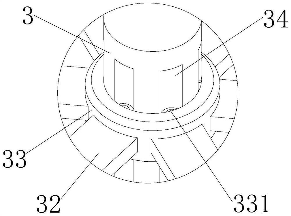
[0034] see Figure 1-8 , The present invention provides a technical solution: a numerical control machine tool cutting fluid separation equipment, comprising a separation cylinder 1, a connection base 11 is fixedly connected to the bottom of the separation cylinder 1, a plurality of reinforcing ribs are fixedly connected on the surface of the connection base 11, and the separation cylinder 1 A drain pipe 12 is fixedly connected on th...


PUM


Abstract

The invention discloses numerical control machine tool cutting fluid separation equipment which comprises a separation barrel, a connecting base fixedly connected to the bottom of the separation barrel, a plurality of reinforcing ribs fixedly connected to the surface of the connecting base, a drainage pipe fixedly connected to the surface of the separation barrel, a feeding hopper fixedly connected to the surface of the separation barrel, and a supporting plate fixedly connected to the feeding hopper. A transmission shaft is rotatably arranged at the bottom of the supporting plate, a limiting ring is fixedly connected to the inner wall of the separation cylinder, a separation funnel is rotatably arranged in the limiting ring, and a plurality of drainage holes are formed in the separation funnel; compared with the prior art, the welding ring can be driven to rotate through the transmission shaft, so that the separation funnel does circular motion, cutting fluid and metal cuttings can be rapidly separated, the situation that rust is caused due to the fact that part of the cutting fluid remains on the surfaces of the metal cuttings is reduced, and the service life of the cutting fluid can be prolonged; and good economic benefits are achieved.

Description

technical field [0001] The invention relates to the technical field of numerical control machining, in particular to a cutting fluid separation device for numerically controlled machine tools. Background technique [0002] In the process of mechanical manufacturing, the cutting process will be involved. In the process of cutting, cutting fluid will be used. The main functions of cutting fluid are cleaning, rust prevention, lubrication and cooling. [0003] If the cutting fluid contains impurities, it will seriously affect the machining of the tool and damage the production equipment. The metal impurities in the cutting fluid will remain in the cutting fluid tank for a long time, and will also react with the cutting fluid, resulting in the deterioration of the cutting fluid. To reduce the anti-rust performance of the cutting fluid and shorten the service life of the cutting fluid, in the industrial production process, the cutting fluid will be processed by the cutting fluid s...

Claims


Application Information

Patent Timeline
Patent Type & Authority Applications(China)
IPC IPC(8): B04B15/06B23Q11/00B23Q11/10
CPCB23Q11/1069B23Q11/10B23Q11/00B04B15/06
Inventor 方卫国
Owner 方卫国
Why Eureka
Try Eureka