
Production line for machining pipe ends of pipes

A production line and pipe technology, applied in metal processing equipment, metal processing machinery parts, manufacturing tools, etc., can solve the problems of long alignment process, slow cutting speed, long cutting time, etc., and achieve the effect of simple structure and ingenious conception

Pending Publication Date: 2022-06-17
SUZHOU KINKALTECK MACHINERY TECH
View PDF0 Cites 1 Cited by
  • Summary
  • Abstract
  • Description
  • Claims
  • Application Information

AI Technical Summary

Problems solved by technology

[0002] After the steel pipe is formed through a series of processes, it is necessary to transfer the steel pipe to the cutting equipment through the relevant mechanism of transferring and feeding, and cut the head and tail of the two ends of the steel pipe. At present, the relevant mechanism of transferring and feeding is The structure of multiple steel pipes being fed simultaneously in batches requires a process of aligning (or flattening) the ends of multiple steel pipes before cutting the head and tail. The alignment process is complicated, especially when the lengths of the steel pipes are inconsistent. The process takes a long time, which affects the processing efficiency; in addition, at the present stage, the cutting of the ends of multiple steel pipes at the same time is done through a band saw. The cutting speed is slow and the cutting time is long, which will also affect the processing efficiency.

Method used


Image

  • Production line for machining pipe ends of pipes
  • Production line for machining pipe ends of pipes
  • Production line for machining pipe ends of pipes

Examples


Embodiment Construction

[0051] The present invention will be further described in detail below through specific embodiments.

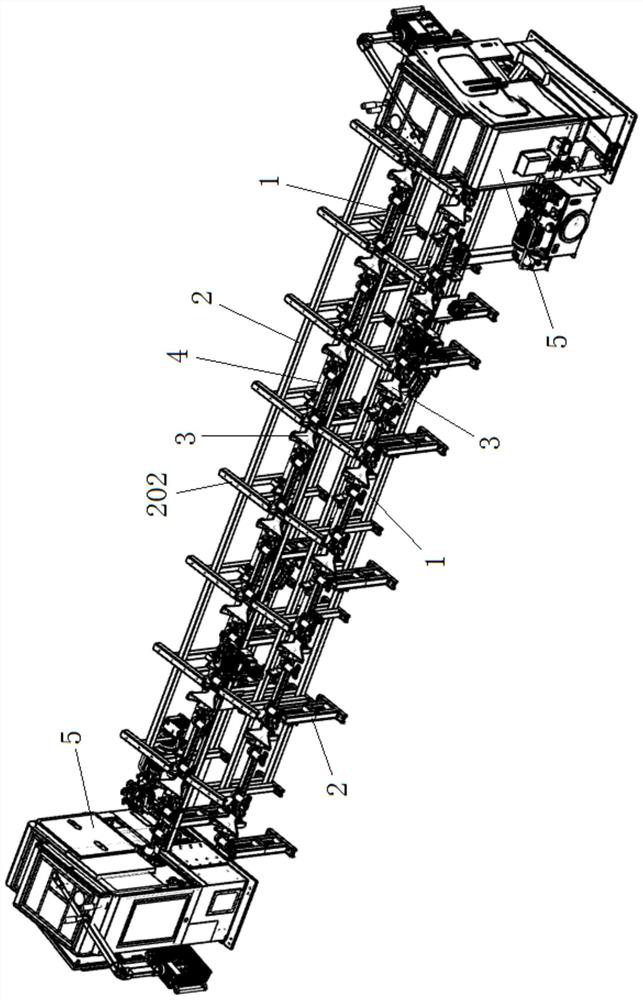
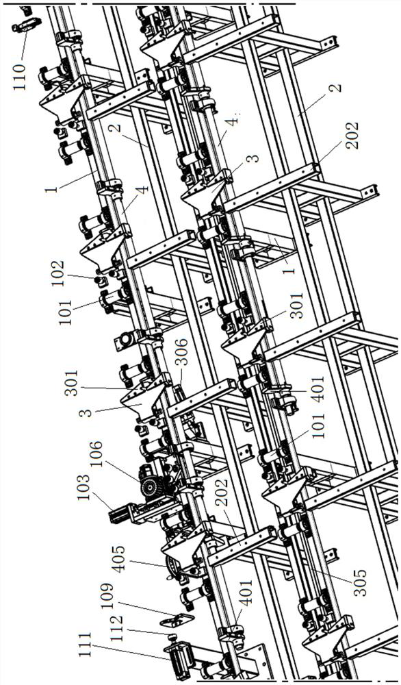
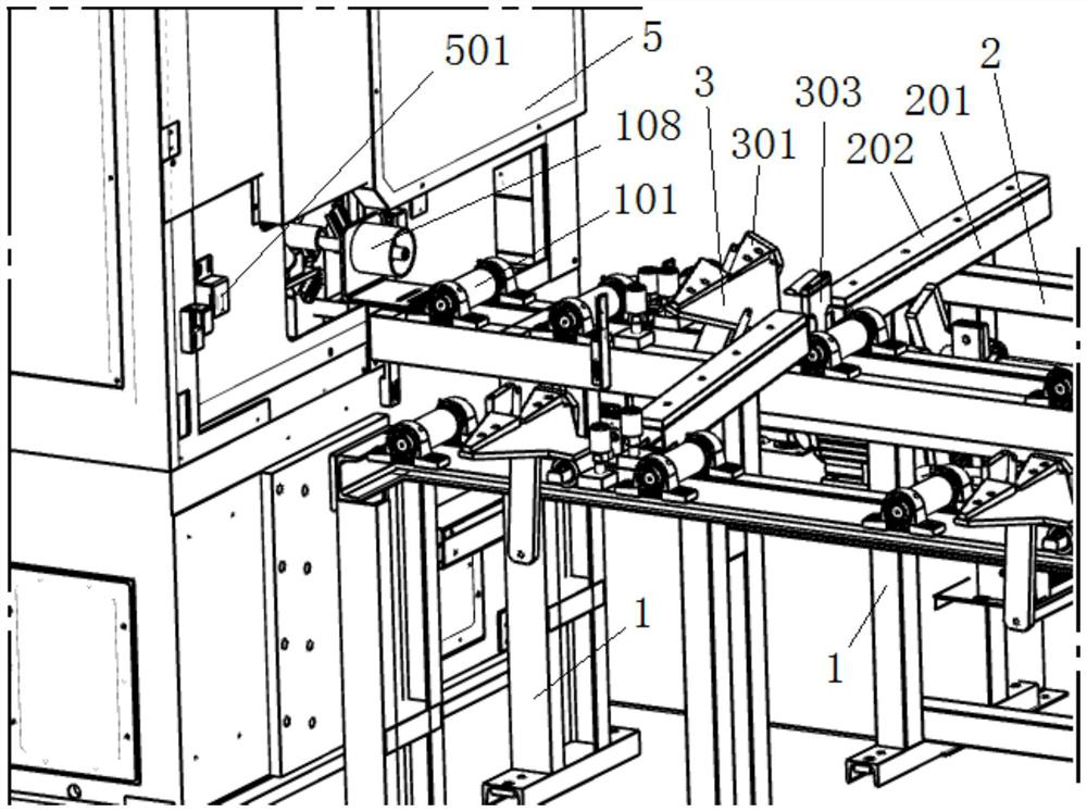
[0052] like Figure 1 to Figure 9 As shown in common, a production line for pipe end processing includes two sets of feeding racks with the same structure and arranged side by side, both of which are provided with a pipe feeding device for conveying the pipe body one by one, located in the pipe feeding device. The upstream feeding racks are all provided with inclined pipe guiding structures, and the pipe guiding structures located on the downstream feeding racks extend in the direction of the pipe feeding devices located on the upstream feeding racks; it also includes two pipes distributed at the end of the feeding racks. The sawing machine 5 is used to cut the head and tail of the pipe body respectively. The feeding position of the sawing machine 5 is set corresponding to the feeding direction of the pipe feeding device. The sawing machine is provided with positioning clampi...


PUM


Abstract

The invention discloses a production line for pipe end processing, which comprises two sets of feeding frames which are the same in structure and are arranged side by side, the two feeding frames are both provided with pipe conveying devices for conveying pipe bodies one by one, and the feeding frames located at the upstream of the pipe conveying devices are both provided with obliquely arranged pipe body guiding and conveying structures; the two saw cutting machines are distributed at the end of the feeding frame and are used for cutting the head and the tail of the pipe body respectively, the feeding positions of the saw cutting machines correspond to the feeding direction of the pipe feeding device, and positioning, clamping and removing mechanisms are arranged on the saw cutting machines. Compared with a traditional mode that multiple steel pipes are fed in batches at the same time, head cutting and tail cutting work of the steel pipes is completed in a one-by-one feeding mode, the procedure of aligning the pipe ends is omitted, meanwhile, the pipe ends are cut off through the sawing machine, the cutting speed is high, a large amount of time is saved, and the working efficiency is greatly improved.

Description

technical field [0001] The invention belongs to the technical field of seamless steel pipe end cutting, and in particular relates to a production line for pipe end processing. Background technique [0002] After the steel pipe is formed through a series of processes, the steel pipe needs to be transferred to the cutting equipment through the relevant mechanism for transferring and feeding, and the ends of the steel pipe are cut to the head and tail. The structure of feeding multiple steel pipes in batches at the same time requires the process of aligning (or flattening) the ends of multiple steel pipes before cutting the head and cutting the tail. The alignment process is complicated, especially when the length of the steel pipes is inconsistent, the alignment The process takes a long time, which affects the processing efficiency. In addition, at this stage, the cutting of the heads and tails of multiple steel pipe ends at the same time is done by a band saw. The cutting spe...

Claims


Application Information

Patent Timeline
IPC IPC(8): B23D45/12B23D45/10B23D47/04B23Q17/22
CPCB23D45/12B23D45/10B23D47/042B23D47/04B23Q17/22
Inventor 柯晓华
Owner SUZHOU KINKALTECK MACHINERY TECH
Learn More